Supercharge Your Innovation With Domain-Expert AI Agents!

Video signal processing apparatus, video signal processing method and video source determining method

a video signal and video signal technology, applied in the direction of signal generators with optical-mechanical scanning, color signal processing circuits, television systems, etc., can solve the problems of lowering resolution, not being able to effectively perform the line doubling process, and not being able to display a favorable picture on a television receiver based on the output video signal, so as to supply favorable pictures, and increase the probability of detection

Inactive Publication Date: 2007-10-16
SONY CORP
View PDF8 Cites 26 Cited by
  • Summary
  • Abstract
  • Description
  • Claims
  • Application Information

AI Technical Summary

Benefits of technology

[0010]It is an object of the present invention to provide a video signal processing apparatus and a video signal processing method that make it possible to display favorable pictures on a television receiver by increasing the accuracy of a determination relating to the video source of an input video signal and by using an appropriate scanning method for an output video signal in accordance with the determined type of video source.
[0011]In the video signal processing apparatus and the video source determining method according to the present invention, a calculating means calculates the degree of similarity or degree of difference between the picture of a field provided by a video signal and the picture of a field provided by a delayed video signal produced by delaying the video signal by the equivalent of two fields, the threshold setting means outputs a threshold for determining whether the pictures in each field match, the comparison means compares a calculated value relating to the degree of similarity or degree of difference with the threshold, determines whether the pictures of each field match, and outputs a compare signal showing that the pictures match or do not match, and the signal pattern detecting means detects a signal pattern for the compare signal and determines whether the video source is a film source. By doing so, it is possible to set an appropriate threshold corresponding to a variety of reception conditions, video signal input states, etc., and it is possible to flexibly set the conditions used when determining whether the pictures of fields match or do not match, so that the probability of detecting a signal pattern showing that the video source is a film source can be increased, which has the effect of making it possible to supply a line doubling device with an appropriate combination of video signals with a high probability and to supply favorable pictures.
[0012]In the video signal processing apparatus and the video source determining method according to the present invention, a state that changes according to a determination result relating to the video source is specified in the state transition means, and different thresholds are outputted in at least two states that are a state where the video source is determined to be a film source and a state where the video source is determined to not be a film source. By doing so, by setting a threshold in accordance with the determination result relating to the video source, the probability of detecting a signal pattern showing that the video source is a film source can be increased, which has the effect of making it possible to supply a line doubling device with an appropriate combination of video signals with a higher probability and to supply favorable pictures.

Problems solved by technology

Accordingly, since the combination of video signals supplied to the line doubling device differs between the case when a film source is the video source and the case when a film source is not the video source, if a film source is used as the video source and video signals of three consecutive fields are inputted into the line doubling device, problems such as a lowering of resolution occur and it is not possible to perform the line doubling process effectively.
However, a video signal processing apparatus that includes a conventional line doubling device is constructed as described above, and in a case where the judgment performed for the video source of the input video signal has low accuracy or when a suitable scanning method is not used for the output video signal in accordance with the determined type of video source, there has been the problem that it has not been possible to display a favorable picture on a television receiver based on the output video signal obtained from the line doubling device.

Method used


Image

  • Video signal processing apparatus, video signal processing method and video source determining method
  • Video signal processing apparatus, video signal processing method and video source determining method
  • Video signal processing apparatus, video signal processing method and video source determining method

Examples


embodiment 1

An Exemplified Practical Embodiment 1

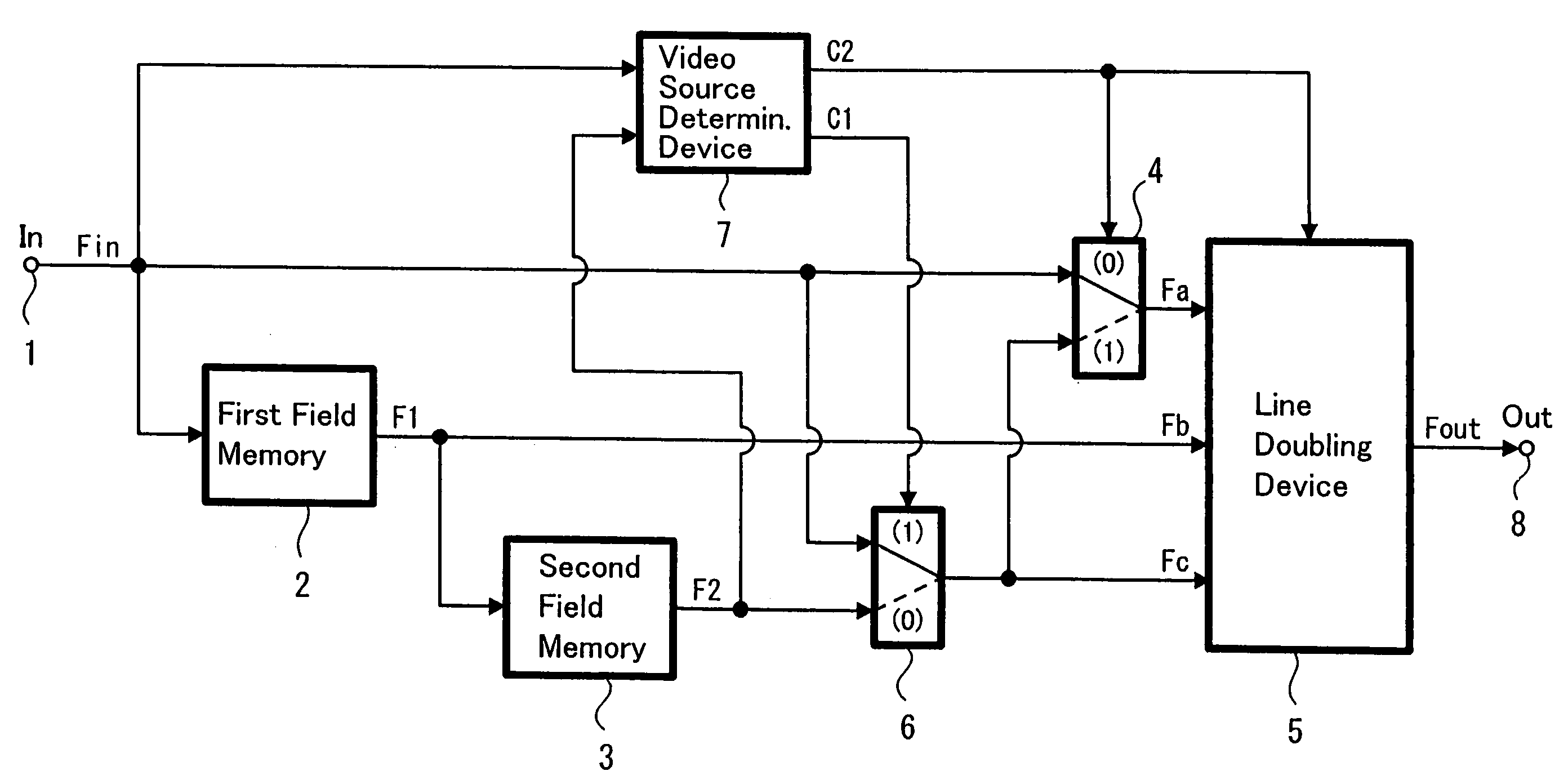
[0034]FIG. 3 is a block diagram showing a video signal processing apparatus according to a first embodiment of the present invention. In FIG. 3, reference numeral 1 denotes an input terminal for inputting a video signal, reference numeral 2 denotes a first field memory for inputting a video signal, delaying the video signal for the time required to input a video signal for one field into the input terminal 1, and then outputting the video signal, reference numeral 3 denotes a second field memory for inputting a video signal, delaying the video signal for the time required to input a video signal for one field into the input terminal 1, and then outputting the video signal, reference numeral 4 denotes a switching circuit that has two inputs and one output and selectively outputs an input signal that has been inputted into one of the inputs in accordance with a control signal, reference numeral 5 denotes a line doubling device (line doubling means)...

embodiment 2

An Exemplified Practical Embodiment 2

[0053]FIG. 10 is a block diagram showing the construction of a video source determining device in a video signal processing apparatus according to a second embodiment of the present invention. In FIG. 10, the same reference numerals as FIG. 6 show the same or equivalent parts, so description of such has been omitted. Reference numeral 31 denotes a noise level detecting means that detects the electric field strength of a received broadcast wave, for example, and specifies the noise level of a video signal.

[0054]Next, the operation of the video signal processing apparatus according to the second embodiment is described. Processes such as the generation process for the video signals F1, F2, Fa, Fb, Fc, etc., the combination changing process for the video signals supplied to the line doubling device 5 based on the determination result of the video source, the counting process for the degree of difference between the pictures of each field, the determ...

embodiment 3

An Exemplified Practical Embodiment 3

[0057]FIG. 13 is a block diagram showing the construction of a video signal processing apparatus according to a third embodiment of the present invention. In FIG. 13, the same reference numerals as FIG. 3 show the same or equivalent parts, so description of such has been omitted. Reference numeral 41 denotes a scanning method indicator (scanning method indicating means) that inputs a determination signal outputted from the video source determining device 7, as well as a scanning method selecting signal and an automatic progressive indicating signal that are described later and outputs a scanning method indicating signal that indicates the scanning method for the video signal outputted from the line doubling device 5. FIG. 14 is a circuit diagram showing one example of the construction of the scanning method indicator. In FIG. 14, reference numeral 51 denotes an AND gate that inputs the automatic progressive indicating signal and the determination...


PUM


Abstract

There is provided a video signal processing apparatus that makes it possible to realize a favorable display of pictures by increasing the detection accuracy of the video source of an input video signal and by using an appropriate scanning method for an output video signal in accordance with the determined type of video source. The video signal processing apparatus includes video source determining means for determining whether the video source of a video signal is a film source, calculating means for calculating a degree of difference between a picture of a field of the video signal and a picture of a field of a delayed video signal, threshold setting means, comparison means for comparing the degree of difference and a threshold and determining whether the pictures of each field match, and a signal pattern detecting means for detecting a signal pattern of a signal outputted by the comparison means and determining whether the video source is a film source, with the threshold setting means outputting respectively different thresholds in a state where the video source is determined to be a film source and a state where the video source is not determined to be a film source.

Description

TECHNICAL FIELD[0001]The present invention relates to a video signal processing apparatus and a video signal processing method that make it possible to display pictures at high resolution, and in particular relates to a video signal processing apparatus and a video signal processing method that double the scan lines in a field provided by a video signal to increase resolution, and change the scan method of the output video signal in accordance with the type of video source.BACKGROUND ART[0002]Conventionally, a method that increases the vertical resolution of pictures by increasing the number of scan lines in the vertical direction in each field is known as a method for improving the picture quality of video signals that are provided based on methods such as NTSC and PAL. In a line doubling device that performs such processing, three input signals are inputted and a video signal with double the number of scan lines is generated.[0003]The scan line doubling process that generates a fi...

Claims


Application Information

Patent Timeline
IPC IPC(8): H04N7/01H04N11/20H04N5/44
CPCH04N7/0112H04N7/012Y10S348/911H04N7/01
Inventor TOKUHARA, MASAHARUSARUGAKU, TOSHIOKANEKO, NAOKIIMAI, SEIKO
Owner SONY CORP
Features
  • R&D
  • Intellectual Property
  • Life Sciences
  • Materials
  • Tech Scout
  • Unparalleled Data Quality
  • Higher Quality Content
  • 60% Fewer Hallucinations
Learn More