Radar level gauge system

a level gauge and level gauge technology, applied in the direction of liquid/fluent solid measurement, instruments, machines/engines, etc., can solve the problems of difficult to distinguish the filling material surface, difficult to find and track the right surface in the process tank, and general difficulty in typical process applications, so as to achieve the effect of more easily and accurately detection

Active Publication Date: 2007-10-23
ROSEMOUNT TANK RADAR
View PDF18 Cites 35 Cited by
  • Summary
  • Abstract
  • Description
  • Claims
  • Application Information

AI Technical Summary

Benefits of technology

[0036]It is notable that the first and third times may occur essentially simultaneously. In this case, the first transmit signals may be identical to the third transmit signals, even though it may also be possible to use separate transmit signals, having e.g. different polarization. Further, the second and fourth times may occur essentially simultaneously, wherein the second transmit signals may be identical to the fourth transmit signals. However, the times may also be temporally separated. Optionally measurements could be added at one or more further time moments creating a set of measurements enabling more reliable conclusions when e.g. the level and amplitude values are fluctuating due to turbulence, etc.
[0040]The difference analysis of the present invention provides a number of advantages, since the echoes corresponding to the filling material surface could be detected more easily and accurately. Thus, the present invention is usable as a complement to conventional RLG logics, to identify the surface during start-up, during the situation where the empty-tank condition is left, and the tank is starting to be filled, when the filling level passes reflecting structures in the tank, etc. The difference analysis is also useful for distinguishing between the echoes from moving objects, such as agitators, from stationary objects, such as baffles and beams.

Problems solved by technology

Such accuracy is nowadays practically feasible in marine and refinery installations but generally not easy to obtain in typical process applications due to the abundance of disturbing echoes.
Thus, the task of finding and tracking the right surface is much more difficult in a process tank than in for instance a refinery tank.
Further, it is normally difficult to distinguish the filling material surface when the tank is essentially empty and is starting to be filled.
Still further, strong echoes from stationary objects and structures in the tank would intervene in the measurement, and the tracking functionality could easily be fooled to lock on an erroneous echo, or lose the filling material surface echo when close to a disturbing echo.
Unfortunately, a more narrow antenna beam requires a bigger antenna diameter which may be incompatible with existing mounting holes.
Consequently, the number of disturbing echoes occurring in the raw signal generally is bigger than desired in typical process tanks.
These methods may be efficient but unfortunately they require extra hardware, and is therefore normally more expensive and more cumbersome to produce and install.
Further, such system will normally require more time and development resources.
These methods may be efficient but unfortunately they require extra hard-ware, and is therefore normally more expensive and more cumbersome to produce and install.
Further, such system will normally require more time and development resources.

Method used


Image

  • Radar level gauge system
  • Radar level gauge system
  • Radar level gauge system

Examples


Embodiment Construction

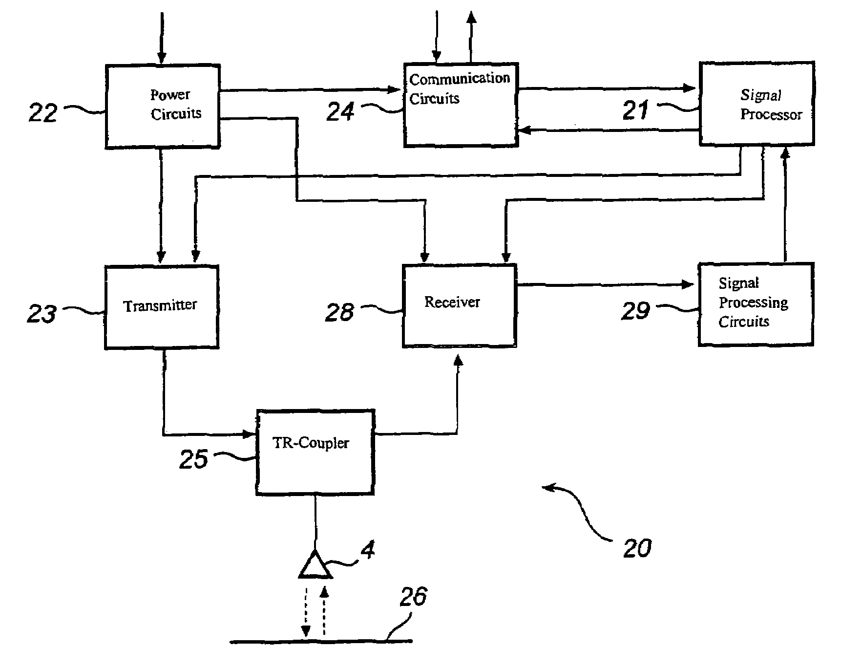
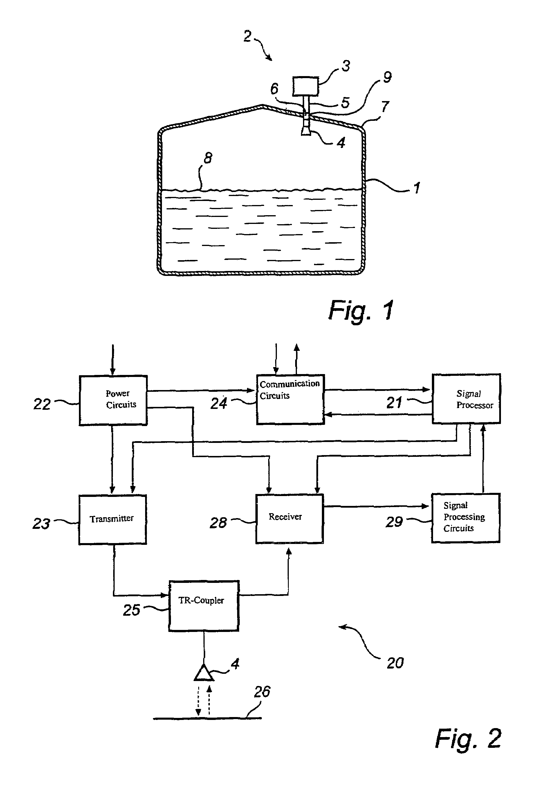
[0085]FIG. 1 shows schematically a radar level gauge system 1 in which the invention may be advantageously incorporated. In brief, the system in FIG. 1 comprises an electronic unit 3 for transmitting and receiving radar signals and processing the received signals in order to determine the level in the tank, an antenna 4 arranged inside the tank for transmitting and receiving radar waves into the tank, and a radar wave guide assembly 5 for guiding signals between the electronic unit 3 and the antenna 4. The same antenna could preferably be used both as a transmitter for emitting the output radiation and as a receiver for receiving the reflected echo signal, even though it is also possible to use separate antennas for these functions. The exemplifying embodiments of the invention uses radar antennas providing a free radar beam, in which case disturbing echoes are particularly frequent, but it is also possible to use the invention in guided radar systems, using a waveguiding structure ...


PUM


Abstract

A method and a system for radar-based gauging of a filling level of a filling material is disclosed, wherein the tank has at least one interfering structure. The method comprises: transmitting at a first time moment a microwave signal towards the surface of the filling material; receiving microwave signals as reflected against the surface of the filling material and as reflected against said at least one interfering structure; calculating based on propagation times of the transmitted and reflected microwave signals at least two distances to reflective surfaces in the tank; and repeating at a second time moment the transmitting, the detecting and the calculating, wherein said first time moment is timely separated from said second time moment. Based on the several repeated measurements, the distance to the surface of the filling material is determined as the calculated distance that exhibits the greatest change between said first and second time moments. Based on this time difference analysis, it is possible to discinguish moving surfaces very easy and acurate. The method is specifically advantageous in overfill or high level alarm systems.

Description

[0001]The present application is based on and claims the benefit of Swedish patent application Serial No. 0403165-4, Dec. 23, 2004, the contents of which are hereby incorporated by reference in their entirety.FIELD OF THE INVENTION[0002]The present invention relates to a radar level gauge system for determining the filling level of a filling material in a tank, comprising a transmitter for emitting measuring signals towards the surface of the filling material; a receiver for receiving echo signals from the tank; and processing circuitry for determining the filling level of the tank based on said echo signal. More specifically the invention relates to a radar level gauge system to be used in tanks having at least one interfering structure which reflects the emitted measuring signals. Further, the invention also relates to a corresponding method for determining the filling level of a filling material in a tank.BACKGROUND OF THE INVENTION[0003]Radar level gauging (RLG) to measure the l...

Claims


Application Information

Patent Timeline
Patent Type & Authority Patents(United States)
IPC IPC(8): G01F23/00G01F23/28G01F23/284G01S
CPCG01F23/284
Inventor WENNERBERG, TOMASEDVARDSSON, OLOV
Owner ROSEMOUNT TANK RADAR
Why Eureka
Try Eureka