
Device and method for passively measuring fluid and target chemical mass fluxes in natural and constructed non-porous fluid flow system

a fluid flow system and target chemical technology, applied in the direction of liquid/fluent solid measurement, volume/mass flow by differential pressure, instruments, etc., can solve the problems of significant pollution problems for nature and society, the majority of the time, and the inability to direct measure the cumulative fluid flux

Active Publication Date: 2007-10-23
UNIV OF FLORIDA RES FOUNDATION INC
View PDF36 Cites 11 Cited by
  • Summary
  • Abstract
  • Description
  • Claims
  • Application Information

AI Technical Summary

Benefits of technology

The present invention provides a highly efficient testing method and apparatus for analyzing target chemicals in fluid flow systems. The device can capture a representative sample of target chemicals in a fluid flow system and analyze them qualitatively and quantitatively. It can measure the mass loads of target chemicals and their associated fluid fluxes simultaneously, without the need for pump systems. The device can also measure the spatial distribution of target chemicals and their associated fluxes in real-time. It is easy to use, requires minimal labor, and avoids waste products. The invention can provide information on the magnitude of target chemical mass flow and fluid flow in a way that allows for effective remediation or pollution control measures. The device can also facilitate the mapping of target chemical mass loadings along the reach of a fluid flow system. The invention can measure the following at specific locations in fluid flow systems: (1) the magnitude of local cumulative fluid fluxes, and (2) the magnitude of local cumulative mass fluxes of target chemicals.

Problems solved by technology

The presence and transport of target chemicals in fluid flow systems can present significant pollution problems to nature and society and can be of great importance to industrial processes.
While the prior methods provide important information regarding the levels of contamination in fluid flow systems of concern, they do not allow direct measurements of target chemical mass fluxes.
And although prior methods and apparatus are capable of measuring instantaneous fluid fluxes, most do not allow direct measurements of cumulative fluid fluxes.
Finally, the commonly used methods that exist do not permit simultaneous measurements of target chemical cumulative mass fluxes and cumulative fluid fluxes.
However, no single method exists for non-porous fluid flow systems that samples vo and C at coincident points in space and time and no method exists to measure cumulative target chemical mass flux and cumulative fluid flux.
For dynamic fluid flow systems, this approach of characterizing target chemical mass flux is subject to significant experimental and conceptual errors.
Thus, any sampling of vo and C that does not occur at coincident points in space and time precludes accurate local estimation of the magnitude of both fluid and target chemical mass fluxes.
Second, the short-term sampling procedures often used to obtain C and vo preclude estimation of the time-integrated (i.e., cumulative) values for fluid flux and target chemical mass flux.
However, target chemical mass loads may still be considerable, even for very high degrees of dilution if the fluid discharge is high enough.
Traditional testing methods also require a large amount of expensive equipment, are labor intensive, and involve complex operating procedures.
Moreover, conventional monitoring techniques which require the removal of numerous fluid samples for individual testing typically generate large quantities of waste products (e.g., residual sample materials) that, if sufficiently contaminated or hazardous by their nature, can present significant disposal problems.

Method used


Image

  • Device and method for passively measuring fluid and target chemical mass fluxes in natural and constructed non-porous fluid flow system
  • Device and method for passively measuring fluid and target chemical mass fluxes in natural and constructed non-porous fluid flow system
  • Device and method for passively measuring fluid and target chemical mass fluxes in natural and constructed non-porous fluid flow system

Examples


Embodiment Construction

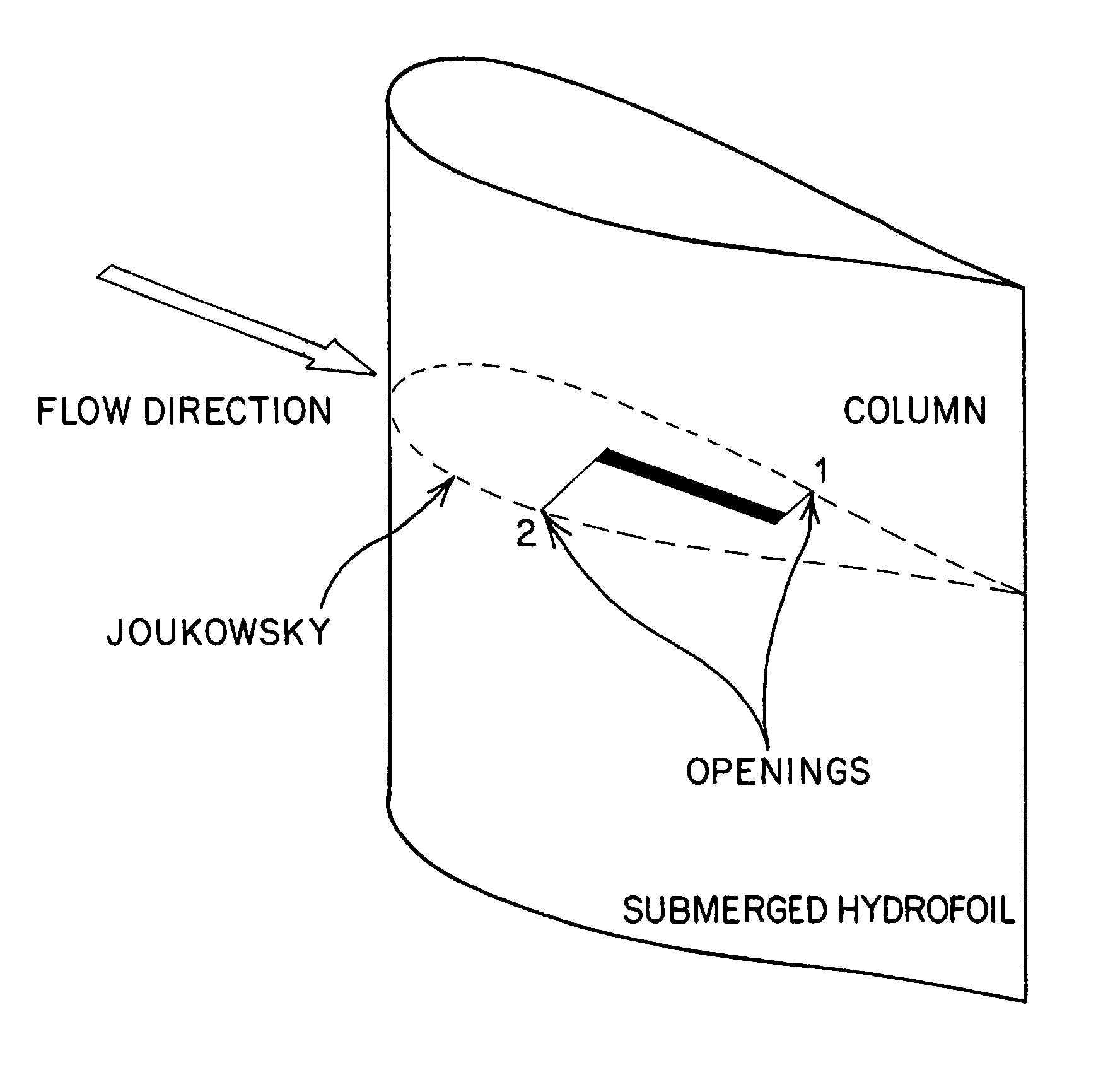
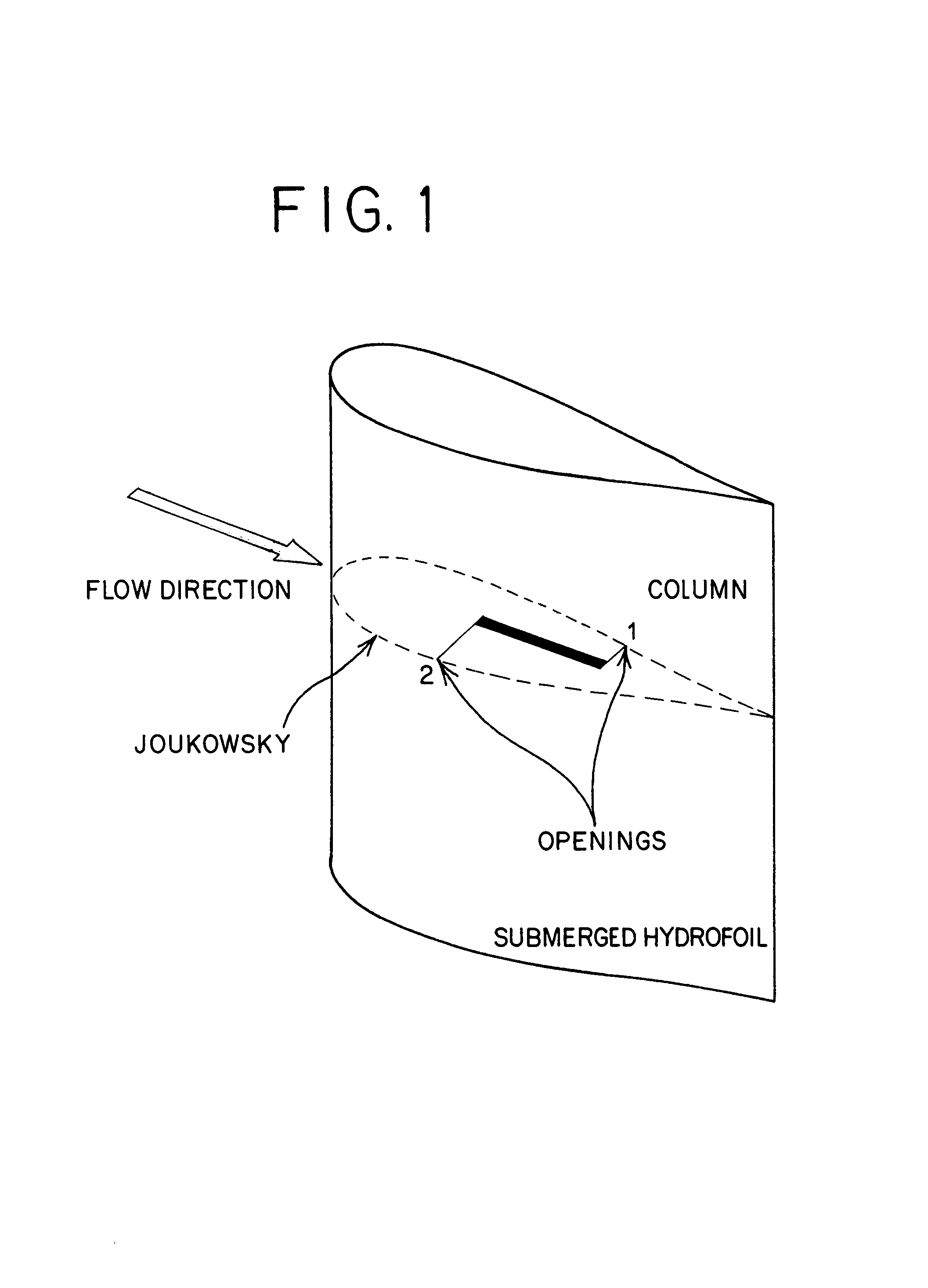
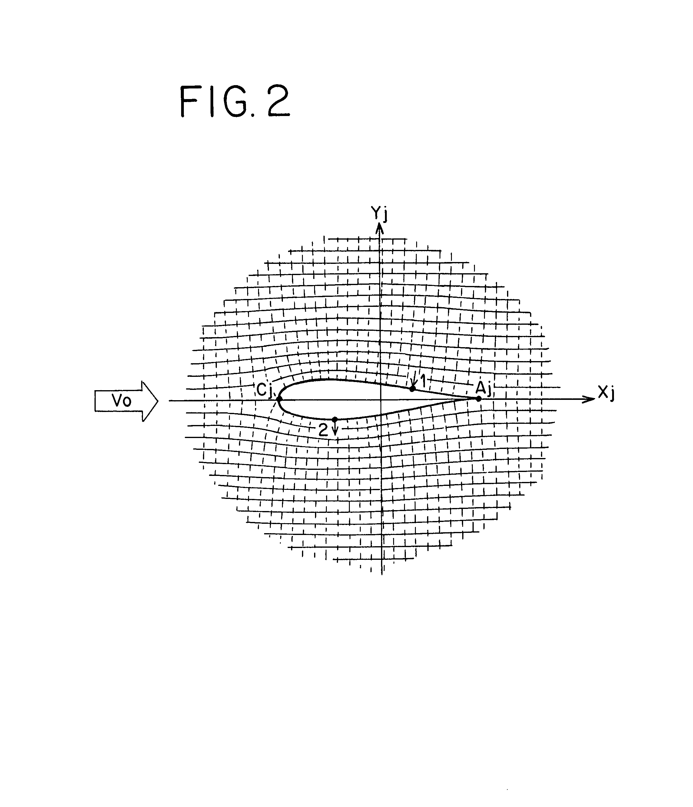
[0035]The claimed invention is designed to simultaneously measure cumulative or time averaged fluid and target chemical mass fluxes in fluid flow systems as defined above. The device is comprised of two major components, a body or shell that is inserted into the flow field, and a bundle of one or more permeable sorptive columns positioned inside or outside the body of the device without disturbing the flow field of the fluid around the device. The extremes of each column are hydraulically connected to the outside flow field around the body of the device through a pair of small openings in the body as illustrated in FIG. 1. The known non-uniform flow velocity distribution around the body of the invention causes a pressure difference between pairs of openings used to connect internal column units. In general each pair of openings is located in the same cross section of the body (e.g., at equal depths below the water surface if the device is installed vertically), and on opposite sides...


PUM


Abstract

An improved method and apparatus for simultaneously monitoring the fluid flux and the target chemical mass fluxes in fluid flow systems is provided comprising the use of a body or shell that is inserted into the flow field. Inside or outside this body is a bundle of one or more permeable sorptive columns. The extremes of each column are hydraulically connected to the outside flow field around the body of the device through a pair of small openings in the body. The known non-uniform flow velocity distribution around the body of the invention causes a pressure difference between pairs of openings used to connect internal or external column units. A preferred shape of the body is a hydrofoil. Alternatively, instantaneous measurement of the fluid flux and contaminant composition is possible using pressure transducers and a chemical sensor. The method of monitoring comprises placing the invention in contact with the contaminated flow field, thereby allowing target chemicals in the fluid to be transported through internal column units and be sorbed on the insoluble sorbent matrix. The permeable sorptive column unit is then removed and the sorptive matrix is analyzed directly or visually (if visible tracers are used) to determine cumulative fluid fluxes and cumulative target chemical mass fluxes.

Description

BACKGROUND OF THE INVENTION[0001]1. Field of the Invention[0002]The present invention generally relates to the detection of organic and inorganic dissolved or gaseous substances in fluids, and, in particular, to the analysis of fluid flow systems for the characterization and quantification of organic and inorganic dissolved or gaseous substances therein. More particularly, this invention relates to devices and methods for measuring cumulative mass fluxes of organic and inorganic dissolved or gaseous substances and cumulative fluid fluxes in fluid flow systems. The term fluid as used herein encompasses any type of liquid or gaseous media (e.g. water or air) containing or not one or more organic and / or inorganic dissolved or gaseous substances (e.g. contaminants or nutrients), while the term flow systems as used herein includes, but is not limited to, constructed flow systems such as closed conduits (e.g. pipes, sewers, vents, stacks, or chimneys) or open conduits (e.g. aqueducts, can...

Claims


Application Information

Patent Timeline
Patent Type & Authority Patents(United States)
IPC IPC(8): G01F1/74
CPCG01F1/40G01N1/12G01N33/18G01N1/40G01N2030/009G01N1/405
Inventor KLAMMLER, HARALD RENEHATFIELD, KIRKJAWITZ, JAMES WILLIAMANNABLE, MICHAEL DAVIDMCDOUGAL, WILLIAM GEORGE
Owner UNIV OF FLORIDA RES FOUNDATION INC
Learn More