Dynamometer tool, in particular a torque wrench, and a method of detecting a break in mechanical equilibrium during tightening to torque

a dynamometer and torque wrench technology, applied in the direction of force/torque/work measurement apparatus, manufacturing tools, instruments, etc., can solve the problems of reliability problems, insufficient construction, relatively short life, etc., and achieve the effect of increasing reliability and not reducing compactness

Inactive Publication Date: 2007-10-23
STANLEY BLACK & DECKER MEA FZE
View PDF18 Cites 9 Cited by
  • Summary
  • Abstract
  • Description
  • Claims
  • Application Information

AI Technical Summary

Benefits of technology

[0008]A main object is to remedy those drawbacks and to provide a mechanical dynamometer tool whose compactness is not reduced and whose reliability is increased.
[0009]Another object is to provide a mechanical dynamometer tool that makes it possible to improve the traceability of the tightening-to-torque operations, by taking account of the phenomenon of over-torque.
[0025]The reception unit is an external station that is external to the tool, and it displays the value of the measurement of the maximum tightening torque applied to the fastener element.

Problems solved by technology

Such a construction is not entirely satisfactory because the housing defines a protuberance on the periphery of the body of the tool, which protuberance is potentially a hindrance to inserting the tool into a mechanical member on which the operator is acting.
In addition, such a construction uses a miniature switch whose life is relatively short and that poses problems of reliability when it is subjected to sudden actuation, which generally applies for tools operating by breaking mechanical equilibrium.
Known devices also suffer from the drawback of not taking account of the phenomenon of over-torque that is exerted during the operation of tightening to torque once the equilibrium is broken.
In addition, the use of electronic dynamometer wrenches is not desired on assembly lines because, with such wrenches, no physical sensation of going beyond the tightening torque can be felt.

Method used


Image

  • Dynamometer tool, in particular a torque wrench, and a method of detecting a break in mechanical equilibrium during tightening to torque
  • Dynamometer tool, in particular a torque wrench, and a method of detecting a break in mechanical equilibrium during tightening to torque
  • Dynamometer tool, in particular a torque wrench, and a method of detecting a break in mechanical equilibrium during tightening to torque

Examples


Embodiment Construction

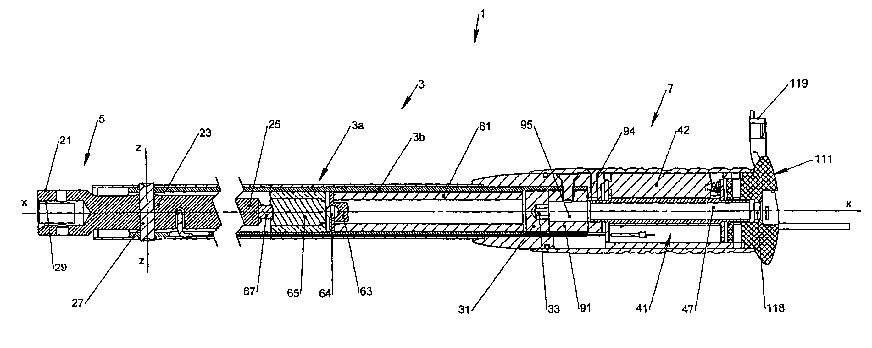
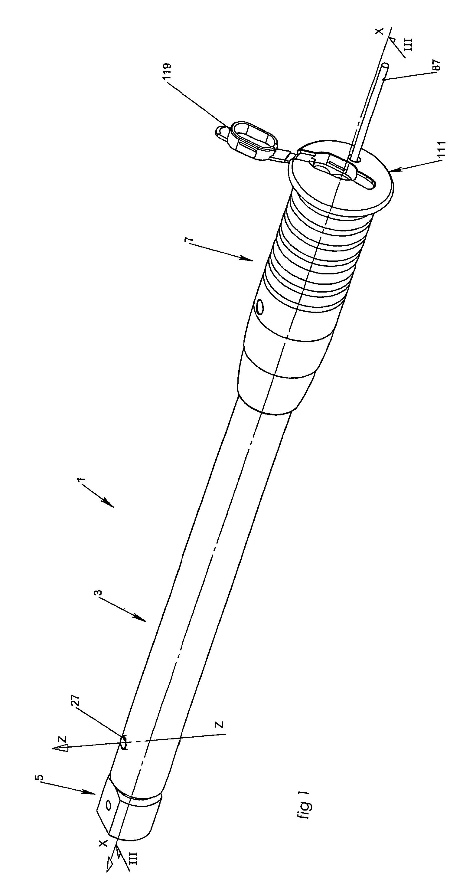
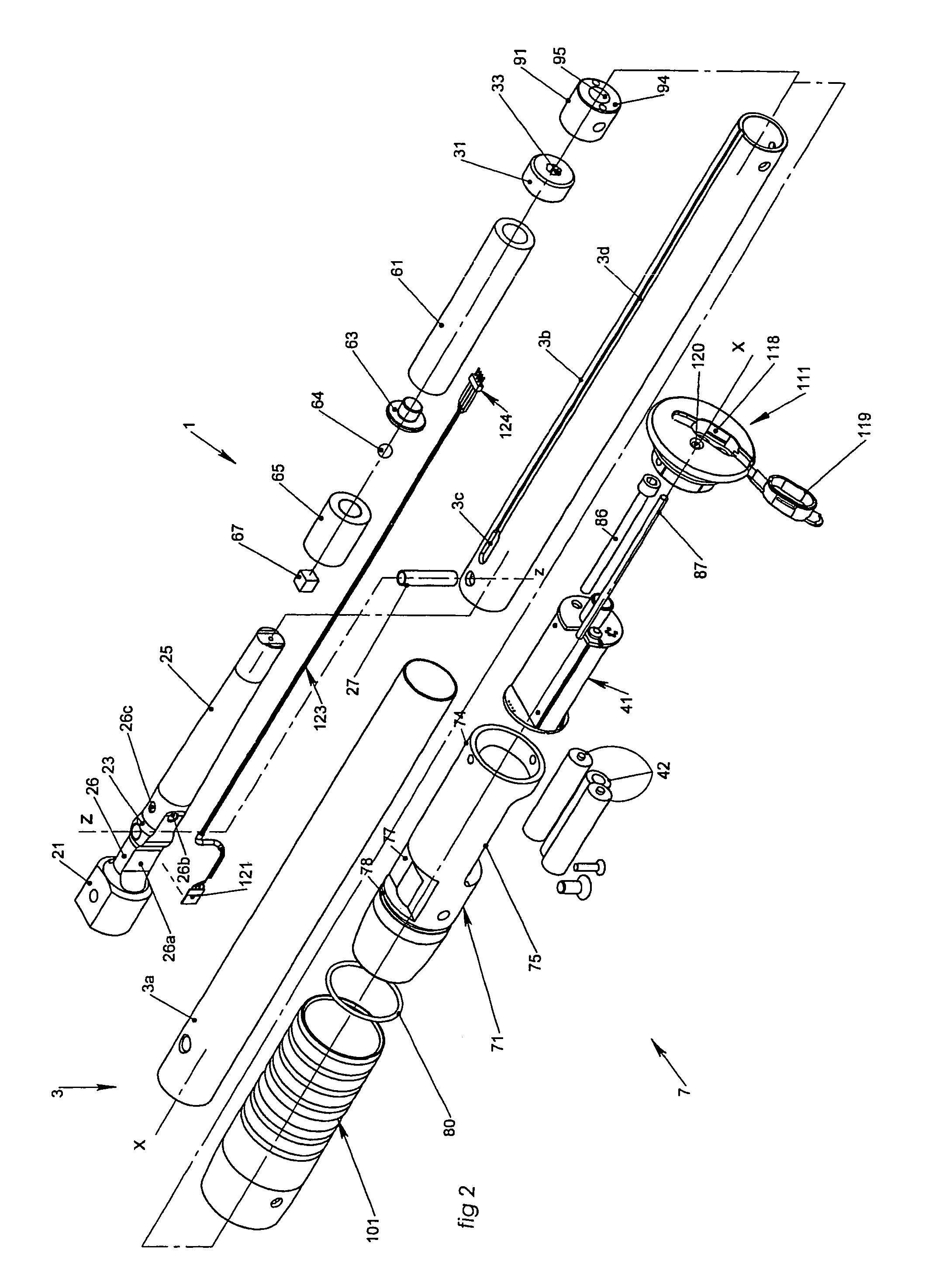
[0045]FIGS. 1 to 3 show a torque wrench of the invention, the wrench having a longitudinal axis X-X, extending from “back” to “front”. The wrench 1 that is shown essentially comprises a tube assembly 3 that is cylindrical in overall shape, and that defines a hollow outer body, a drive element or head 5 in the vicinity of the front of the wrench, and a handle assembly 7 for taking hold of the tool, which handle assembly is situated in the vicinity of the back of the wrench.

[0046]The tube assembly 3 is made up of an outer sheath 3a defined by a cylindrical sleeve, and of an inner tube 3b, the sheath 3a being fitted snugly over the tube 3b and overlapping the tube 3b in the front portion thereof.

[0047]The sheath 3a, the tube 3b and the head 5 are preferably metal parts.

[0048]The wrench shown is a torque setting or disengagement torque wrench of the production type, i.e. of the type used in a production workshop for tightening in succession a large number of identical nut and bolt faste...


PUM


Abstract

A means for detecting a break in mechanical equilibrium comprised of a measurement means that delivers a signal corresponding to a measurement of a torque applied to a fastener element, an electronic processing means for electronically processing a signal, and a computation processing means for computationally processing data output from the electronically processing of the signal. Application to a hand dynamometer tool.

Description

BACKGROUND OF THE INVENTION[0001]The present invention relates to a mechanical dynamometer tool, in particular a torque wrench, for manually applying torque, more specifically the dynamometer tool includes a mechanical means suitable for delivering predetermined torsion torque to a drive portion designed to co-operate with a tightening drive member for driving a fastener element, the mechanical means being in mechanical equilibrium under the action of suitable bias means, the mechanical means being releasable by breaking the mechanical equilibrium, and means for detecting a break in mechanical equilibrium.[0002]It is known that operations for tightening fastener elements in industrial environments require increasing levels of traceability, i.e. knowledge of all of the information and of the measures that make it possible to monitor and to reconstruct rapidly the steps of the process.[0003]For tightening operations, dynamometer tool manufacturers propose mechanical tools whose princi...

Claims


Application Information

Patent Timeline
Patent Type & Authority Patents(United States)
IPC IPC(8): B25B23/14B25B23/144B25B23/159B25B13/06B25B15/02B25B23/142B25B23/143B25B23/155
CPCB25B23/1427B25B23/1425
Inventor CUPIF, BERTRANDPRAUDEL, PHILIPPEVECCHIO, JOCELYN
Owner STANLEY BLACK & DECKER MEA FZE
Why Eureka
Try Eureka