Method and apparatus for non-contact three-dimensional surface measurement

a three-dimensional surface and measurement method technology, applied in the direction of measurement devices, instruments, material analysis, etc., can solve the problems of pixel out of focus measurement with insufficient accuracy, pixel reduction between steps, and measurement accuracy degradation, so as to achieve significant extension of measurement range, high accuracy, and high accuracy

Active Publication Date: 2007-10-23
MITUTOYO CORP
View PDF21 Cites 88 Cited by
  • Summary
  • Abstract
  • Description
  • Claims
  • Application Information

AI Technical Summary

Benefits of technology

[0018]The present invention was developed to solve the aforementioned conventional problems. It is therefore an object of the invention to provide a simple configuration which can be reduced in size and provides an extended measurement range in the direction of depth to realize measurement with high accuracy across the entire measurement range.
[0025]According to the present invention, the order of a fringe in a grating pattern is determined from a focal center, the phase is unwrapped, and the absolute value of the phase is determined in the direction of depth (Z), while the focus is successively shifted. This allows the measurement range to be significantly extended in the direction of depth while measurement is carried out with high accuracy. Additionally, since three-dimensional coordinates are calculated from a phase in which focus is achieved at each pixel, the coordinates can be determined when focus is achieved at all measurement points, thus enabling measurement with high accuracy in the X and Y directions.

Problems solved by technology

Therefore, the measurement range is limited to either one of A, B, C, D, . . . . A measurement range within the order of one fringe would cause the grating spacing to be widened, resulting in degradation in measurement accuracy.
Additionally, when compared with a pixel in focus, a pixel out of focus is measured with insufficient accuracy.
On the other hand, according to Non-patent Document 1, a less number of measurement steps would produce an error in fitting the Gaussian function to determine the maximum contrast, thereby causing a point to be located with reduced accuracy between steps.
This would also make the system complicated because of the movements of the work or the illuminating and the imaging optical systems.
Furthermore, the measurement range in the direction of depth can be increased by increasing the number of steps; however, constraints were placed on the measurement time and the system itself.

Method used


Image

  • Method and apparatus for non-contact three-dimensional surface measurement
  • Method and apparatus for non-contact three-dimensional surface measurement
  • Method and apparatus for non-contact three-dimensional surface measurement

Examples


Embodiment Construction

[0060]Now, the present invention will be described below in more detail with reference to the accompanying drawings in accordance with the preferred embodiments.

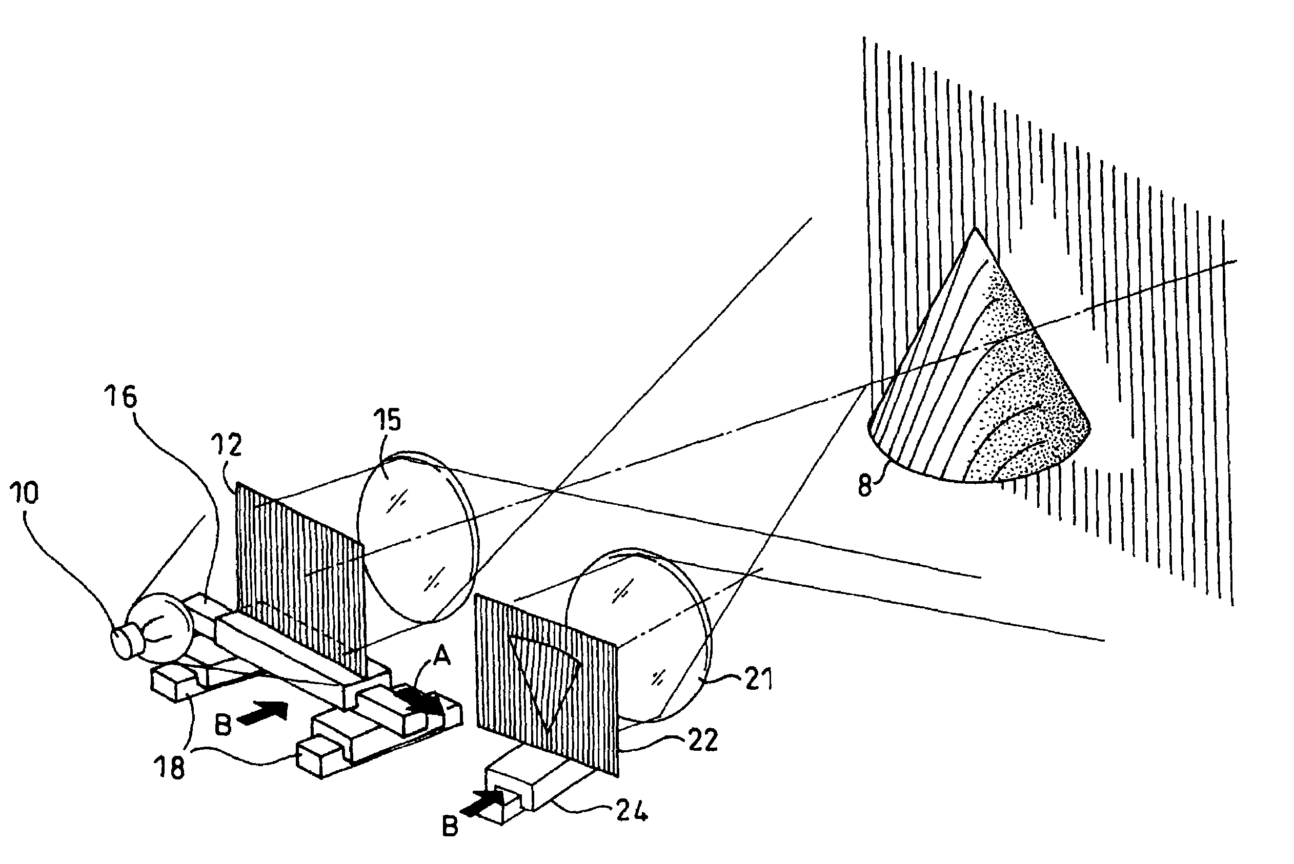
[0061]FIG. 5 illustrates the overall configuration of an apparatus for implementing the present invention.

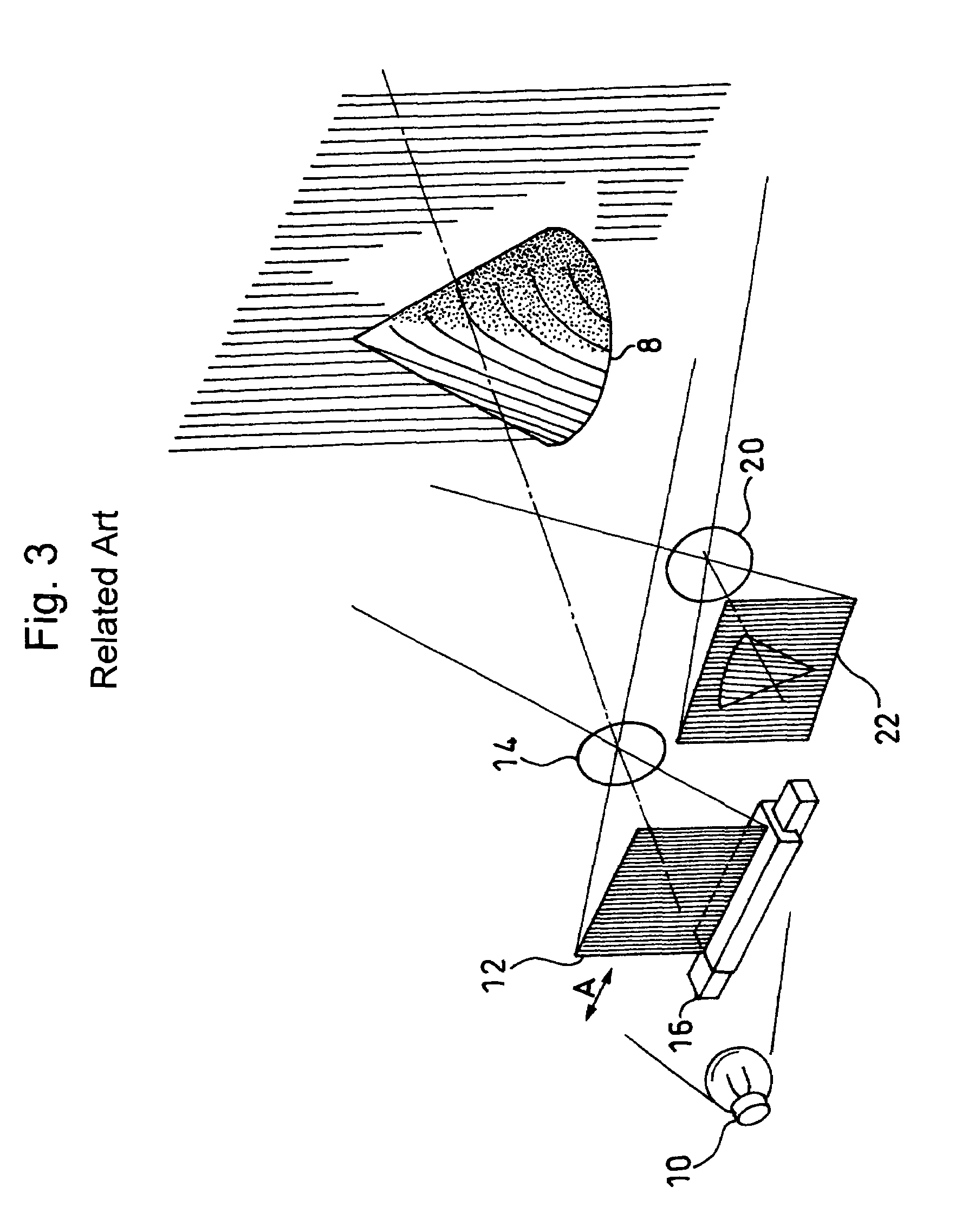
[0062]This embodiment relates to an apparatus similar to the conventional one shown in FIG. 3, in which further included are a first focus shift mechanism 18 for moving the grating filter 12 back and forth in the direction as shown by arrow “B” at a constant speed in conjunction with the grating shift mechanism 16 adapted to move the grating filter 12 in the horizontal direction as shown by arrow “A” at a constant speed, and a second focus shift mechanism 24 for moving the imaging device 22 such as a camera back and forth in the direction shown by arrow “B” at a constant speed. The apparatus according to this embodiment is provided with a projection lens 15 and an imaging lens 21 as an image side telecentric optical syst...


PUM


Abstract

A non-contact three-dimensional surface measurement method is provided in which a grating pattern projected onto an object being measured, while the phase of the pattern is being shifted, is observed in a different direction from a projection direction to analyze the contrast of a grating image deformed in accordance with the shape of the object and thereby obtain the shape thereof. The method enables measurement of a three-dimensional shape over a large measurement range in a short time in a non-contact manner by successively shifting the focus on the projection and the imaging sides to enlarge the measurement range in the direction of depth.

Description

BACKGROUND OF THE INVENTION[0001]1. Field of the Invention[0002]The present invention relates to a method and an apparatus for non-contact three-dimensional surface measurement, which projects a grating pattern onto an object being measured while the phase of the pattern is being shifted, so that the projected pattern is observed in a different direction from that of the projection to analyze the contrast of a grating image deformed in accordance with the shape of the object and thereby obtain the shape thereof. More particularly, the invention relates to a method and apparatus for non-contact three-dimensional surface measurement which is preferably used for providing digitized data on design features to a CAD system as well as for a non-contact digitizer for evaluating the accuracy in shape of prototype or mass-produced parts (in the field of Reverse Engineering), which enables measurement of three-dimensional shapes such as of a full-scale car over a large measurement range at hi...

Claims


Application Information

Patent Timeline
Patent Type & Authority Patents(United States)
IPC IPC(8): G01B11/24G06K9/36G01B11/25
CPCG01B11/254G01B11/2527
Inventor YOSHIDA, HIROYUKI
Owner MITUTOYO CORP
Why Eureka
Try Eureka