
Method and apparatus for providing quality of service across a switched backplane for multicast packets

a backplane and packet quality technology, applied in the field of computer networks and internetworking communication technologies, can solve problems such as conflict, routers and other network devices are vulnerable to data packet traffic congestion, and routers are suddenly inundated with a sharp increase in traffic, so as to increase the robustness of the messaging system

Active Publication Date: 2007-10-23
EXTREME NETWORKS INC
View PDF8 Cites 28 Cited by
  • Summary
  • Abstract
  • Description
  • Claims
  • Application Information

AI Technical Summary

Benefits of technology

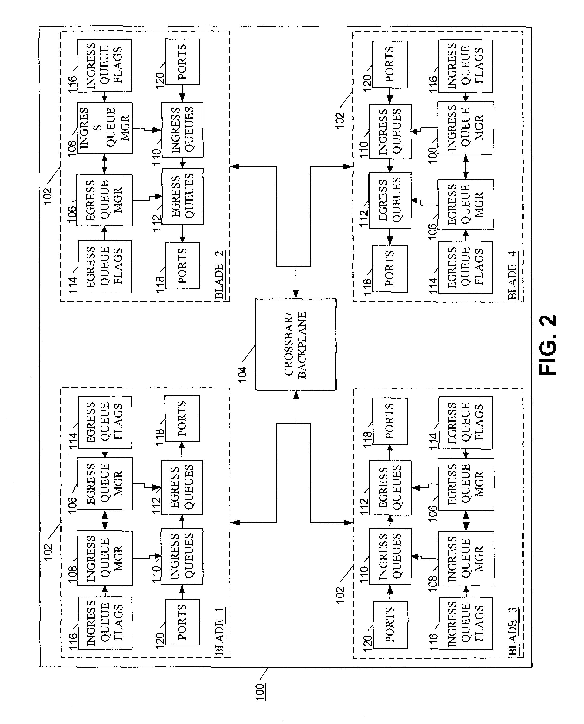
The present invention provides a method for enabling quality of service across a switched backplane using a messaging system. The method involves providing each blade in a router with one or more ingress queues and one or more egress queues. The queues are managed by queue managers that use congestion messages to control traffic. The congestion messages are generated based on the rate of traffic in the queues and the queues are cleared when the traffic falls below a certain threshold. The method also includes a mechanism for propagating the congestion messages to the ingress and egress queue managers on other blades to ensure that quality of service policies are propagated across the switched backplane. The invention allows for the efficient management of congestion control and ensures that normal quality of service is not resumed prematurely.

Problems solved by technology

In today's modern networks, routers and other network devices are vulnerable to data packet traffic congestion.
Because network traffic is typically bursty, it is not unusual for a router to be suddenly inundated with a sharp increase in traffic.
When the network traffic increases, the resulting congestion is typically localized at one or more of the egress queues on one of the blades, while the source of the congestion may be any of the ingress queues on the same blade or on one or more of the other blades.
Conflicts can arise if more than one ingress queue wants to send a data packet to the same egress queue at the same time, or if the rate at which the ingress queue is sending packets exceeds the rate at which the egress queue can receive packets.
One drawback to using the central switched backplane is that the crossbar switch by itself has no QoS capabilities.
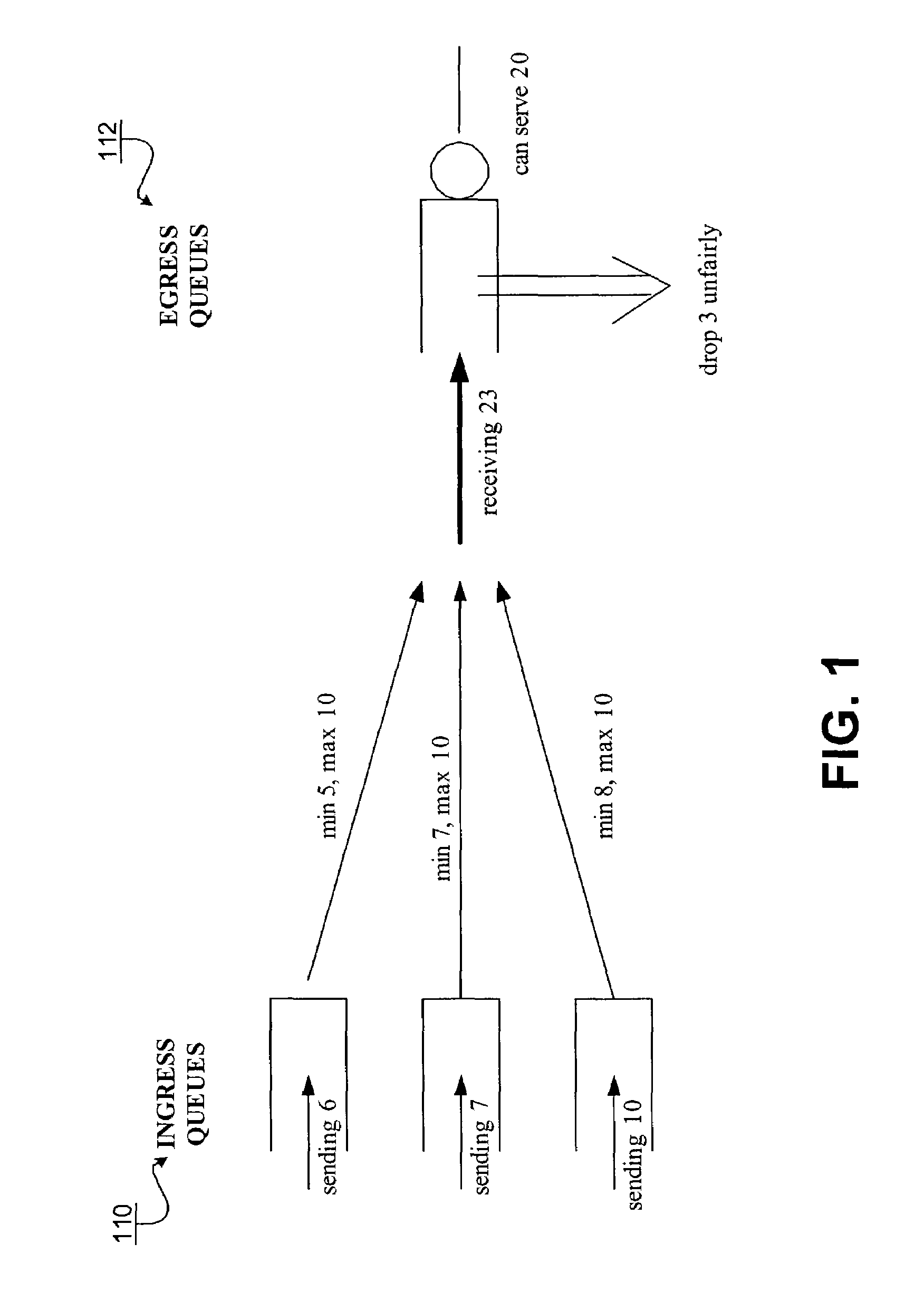
As a result, when the traffic in the queues is transmitted across a backplane channel, the QoS policy for the packet cannot be enforced, and packets may get dropped unfairly.
But dropping the packets is unfair since packets from all three traffic flows are dropped instead of just packets from the offending traffic flows.
However, the TDM scheme is inefficient, as some intervals are wasted when held open even though the corresponding ingress queue has no packet to send.
However, buffering the packets requires memory and memory is expensive.
Moreover, when a single ingress queue is mapped to multiple egress queues, such as when the incoming traffic on several ports of the router is aggregated together into a single ingress queue on a blade, the backpressure mechanism can result in an undesirable head-of-the-line blocking scenario.
A similar undesirable head-of-the-line blocking scenario occurs for multicast traffic, where the multicast traffic to all of the egress queues is slowed down, even though only one or some of the egress queues receiving the multicast traffic are experiencing congestion.
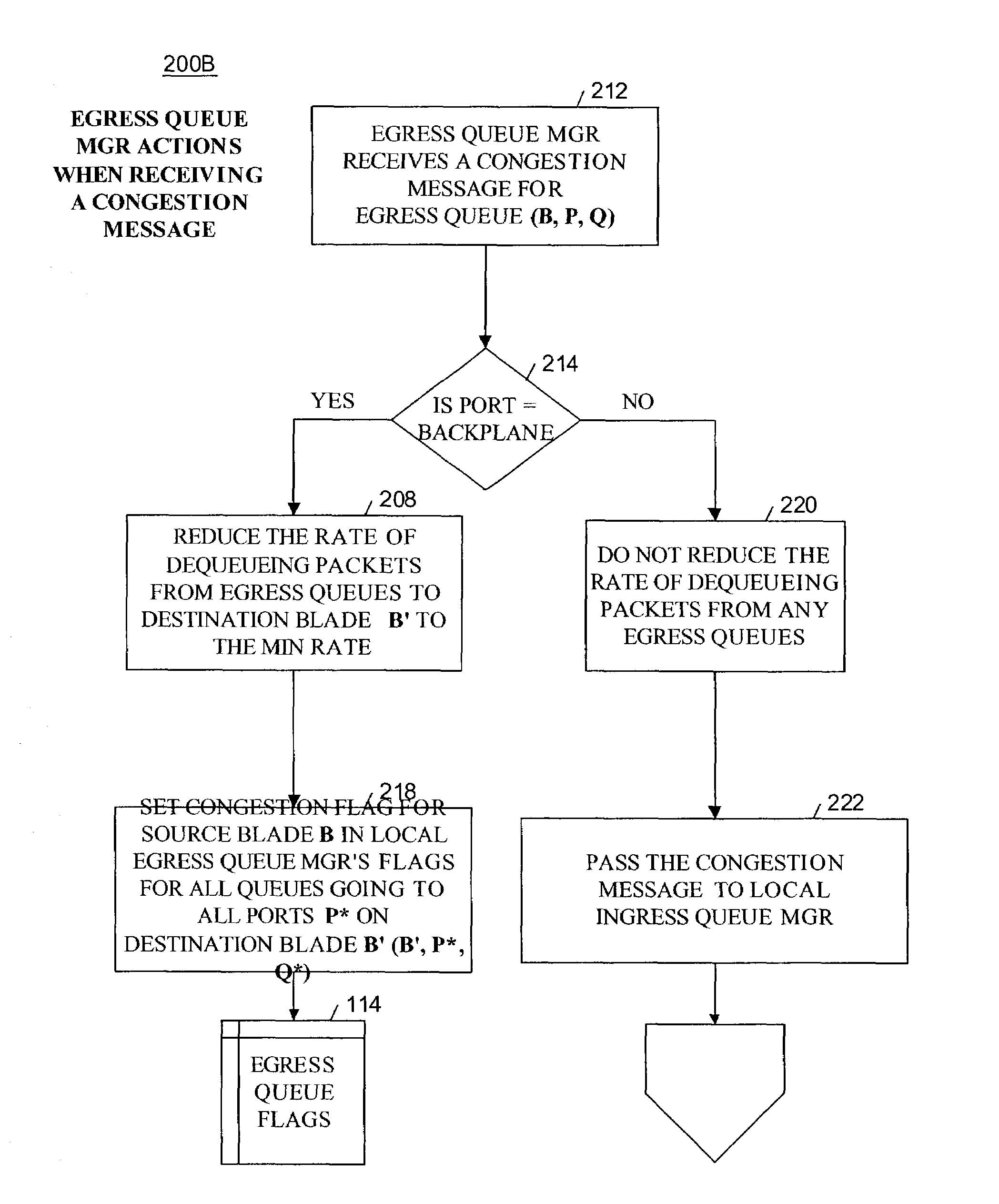
However, when the egress queue in question is a backplane queue, the egress queue manager delays generating a resume message and clearing the congestion flag until the congestion flags indicate that all of the other egress queues mapped to the same destination blade are also not congested.
In addition, the egress queue manager further delays resuming normal packet rates until the congestion flags indicate that all of the egress queues on other blades mapped to the same destination blade are also not congested.

Method used


Image

  • Method and apparatus for providing quality of service across a switched backplane for multicast packets
  • Method and apparatus for providing quality of service across a switched backplane for multicast packets
  • Method and apparatus for providing quality of service across a switched backplane for multicast packets

Examples


Embodiment Construction

[0035]In the following description various aspects of the present invention, a method and apparatus for a messaging system to enable quality of service in a packet forwarding device, will be described. Specific details will be set forth in order to provide a thorough understanding of the present invention. However, it will be apparent to those skilled in the art that the present invention may be practiced with only some or all of the described aspects of the present invention, and with or without some or all of the specific details. In some instances, well known architectures, steps, and techniques have not been shown to avoid unnecessarily obscuring the present invention. For example, specific details are not provided as to whether the method and apparatus is implemented in a router, bridge, server or gateway, or as a software routine, hardware circuit, firmware, or a combination thereof.

[0036]Parts of the description will be presented using terminology commonly employed by those s...


PUM


Abstract

A method and system is provided to enable quality of service across a backplane switch for multicast packets. For multicast traffic, an egress queue manager manages congestion control in accordance with multicast scheduling flags. A multicast scheduling flag is associated with each egress queue capable of receiving a packet from a multicast ingress queue. When the multicast scheduling flag is set and the congested egress queue is an outer queue, the egress queue manager refrains from dequeueing any marked multicast packets to the destination ports associated with the congested outer queue until the congestion subsides. When the congested egress queue is a backplane queue, the egress queue manager refrains from dequeuing any marked multicast packets to the destination ports on the destination blade associated with the congested backplane queue until the congestion subsides.

Description

RELATED APPLICATION DATA[0001]This application is related to pending applications Ser. No. 10 / 188,614, “Method And Apparatus For Providing Quality Of Service Across A Switched Backplane Between Egress Queue Managers”, by Gupta, et al.; and Ser. No. 10 / 213,032, “Method And Apparatus For Providing Quality Of Service Across A Switched Backplane Between Egress and Ingress Queue Managers”, by Gupta, et al.TECHNICAL FIELD[0002]The present invention relates to the field of computer networks and internetworking communications technologies. In particular, the present invention relates to providing quality of service in a network.BACKGROUND AND RELATED ART[0003]In today's modern networks, routers and other network devices are vulnerable to data packet traffic congestion. Because network traffic is typically bursty, it is not unusual for a router to be suddenly inundated with a sharp increase in traffic. Quality of service (QoS) refers to the ability of the network to handle such bursts in tra...

Claims


Application Information

Patent Timeline
Patent Type & Authority Patents(United States)
IPC IPC(8): H04L12/28H04L12/56
CPCH04L12/1881H04L47/10H04L49/505H04L49/201H04L47/30H04L49/101
Inventor GUPTA, RAJARSHICHUEH, JUSTINTANGIRALA, RAVIKASINATHAN, MEERASWENSON, ERIK
Owner EXTREME NETWORKS INC
Learn More