Method and apparatus for adaptive transmission beam forming in a wireless communication system

a wireless communication system and transmission beam technology, applied in the field of antenna beam pattern formation, can solve the problems of reducing the effective time average gain of the antenna, reducing the energy radiated along some angular paths, and not directly applying the techniques of improving the reception of line-of-sight radio systems in multipath signal environments, so as to improve the quality of the received signal of the remote user.

Inactive Publication Date: 2007-10-23
THE BOARD OF TRUSTEES OF THE LELAND STANFORD JUNIOR UNIV +1
View PDF19 Cites 31 Cited by
  • Summary
  • Abstract
  • Description
  • Claims
  • Application Information

AI Technical Summary

Benefits of technology

[0014]Accordingly, it is an object of the invention to provide an adaptive transmit beamforming technique which enhances remote user received signal quality by utilizing the uplink signal energy received from remote users without the need for feedback from the mobile user.
[0017]It is another object of the invention to provide adaptive transmit beam forming which improves signal quality received by a desired user and while simultaneously reducing interference energy received by other undesired users so as to, within a cellular communication network, improve communication traffic capacity, and / or to increase base station coverage area, and / or to improve call quality.SUMMARY OF THE INVENTION

Problems solved by technology

Accordingly, techniques for improving signal reception in line-of-sight radio systems are often not directly applicable to multipath signal environments.
However, if a given antenna beam width is made less than the angular region encompassing the various signal paths comprising a multipath communication channel, further reduction in the beam width may reduce the energy radiated along some of the angular paths.
In turn, this may actually decrease the effective time average gain of the antenna.
This arises because of the inability of the traditional fixed beam approach to sense the interference power delivered to undesired users.
While the process of transmit beamforming to a fixed location over a line-of-sight radio channel may be performed with relative ease, the task of transmitting to a mobile user over a time-varying multipath communication channel is typically considerably more difficult.
Unfortunately, obtaining accurate estimates of the AOA spectrum for communications channels comprised of numerous multipath constituents has proven problematic.
Resolving the AOA spectrum for multiple co-channel mobile units is further complicated if the average signal energy received at the base station from any of the mobile units is significantly less than the energy received from other mobile units.
This is due to the fact that the components of the base station array response vector contributed by the lower-energy incident signals are comparatively small, thus making it difficult to ascertain the AOA spectrum corresponding to those mobile units.
Moreover, near field obstructions proximate base station antenna arrays tend to corrupt the array calibration process, thereby decreasing the accuracy of the estimated AOA spectrum.
One disadvantage of the feedback approach is that the mobile radio needs to be significantly more complex than would otherwise be required.
The resultant capacity reduction may be significant when the remote mobile users move at a high average velocity, as is the case in most cellular telephone systems.
Unfortunately, multipath propagation and other transient channel phenomenon can substantially eliminate any significant equivalence between frequency-duplexed transmit and receive channels, or between time-division duplexed transmit and receive channels separated by a significant time interval.
As a consequence, communication link performance fails to be improved.

Method used


Image

  • Method and apparatus for adaptive transmission beam forming in a wireless communication system
  • Method and apparatus for adaptive transmission beam forming in a wireless communication system
  • Method and apparatus for adaptive transmission beam forming in a wireless communication system

Examples


Embodiment Construction

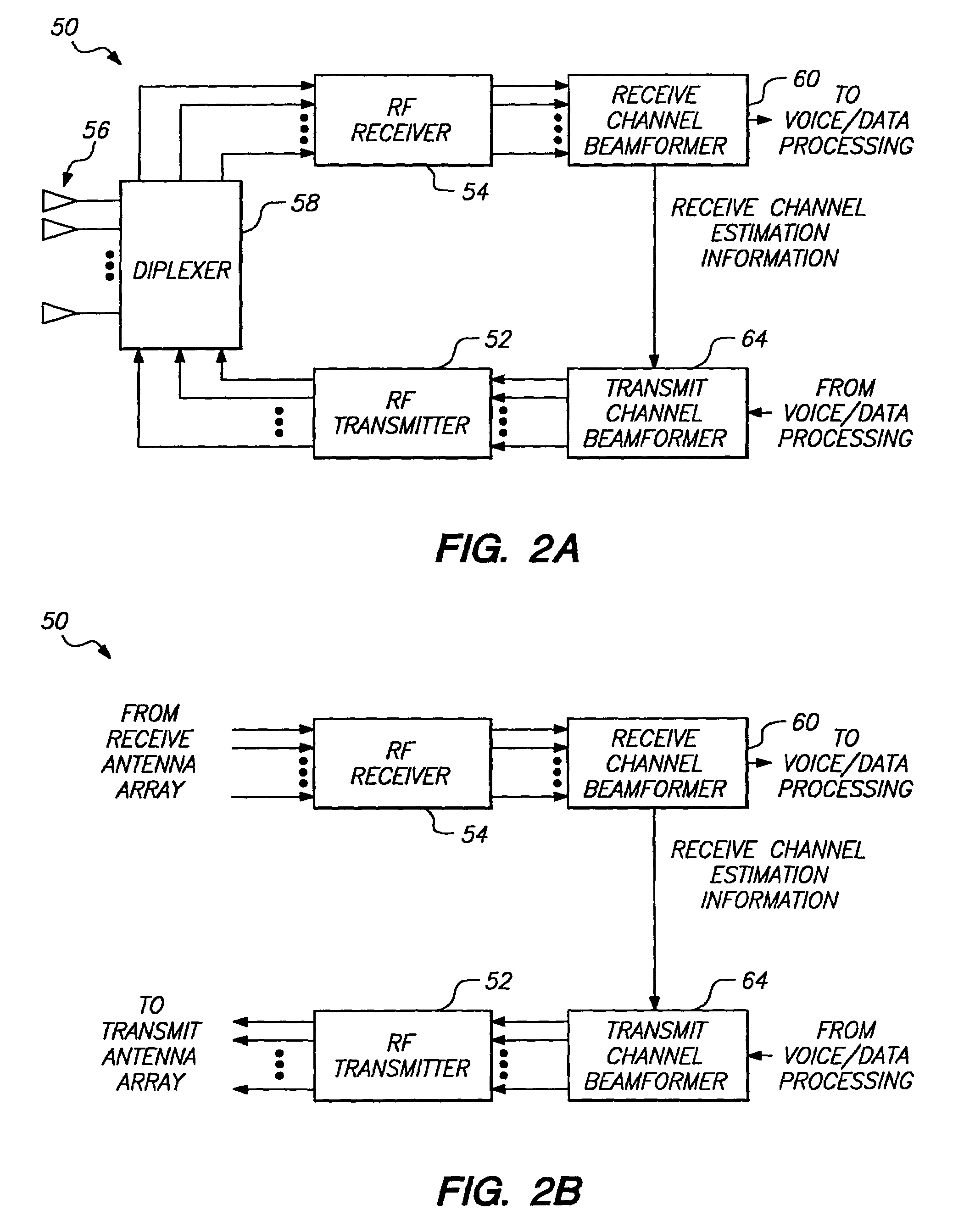
[0033]I. Overview of Beamforming Network

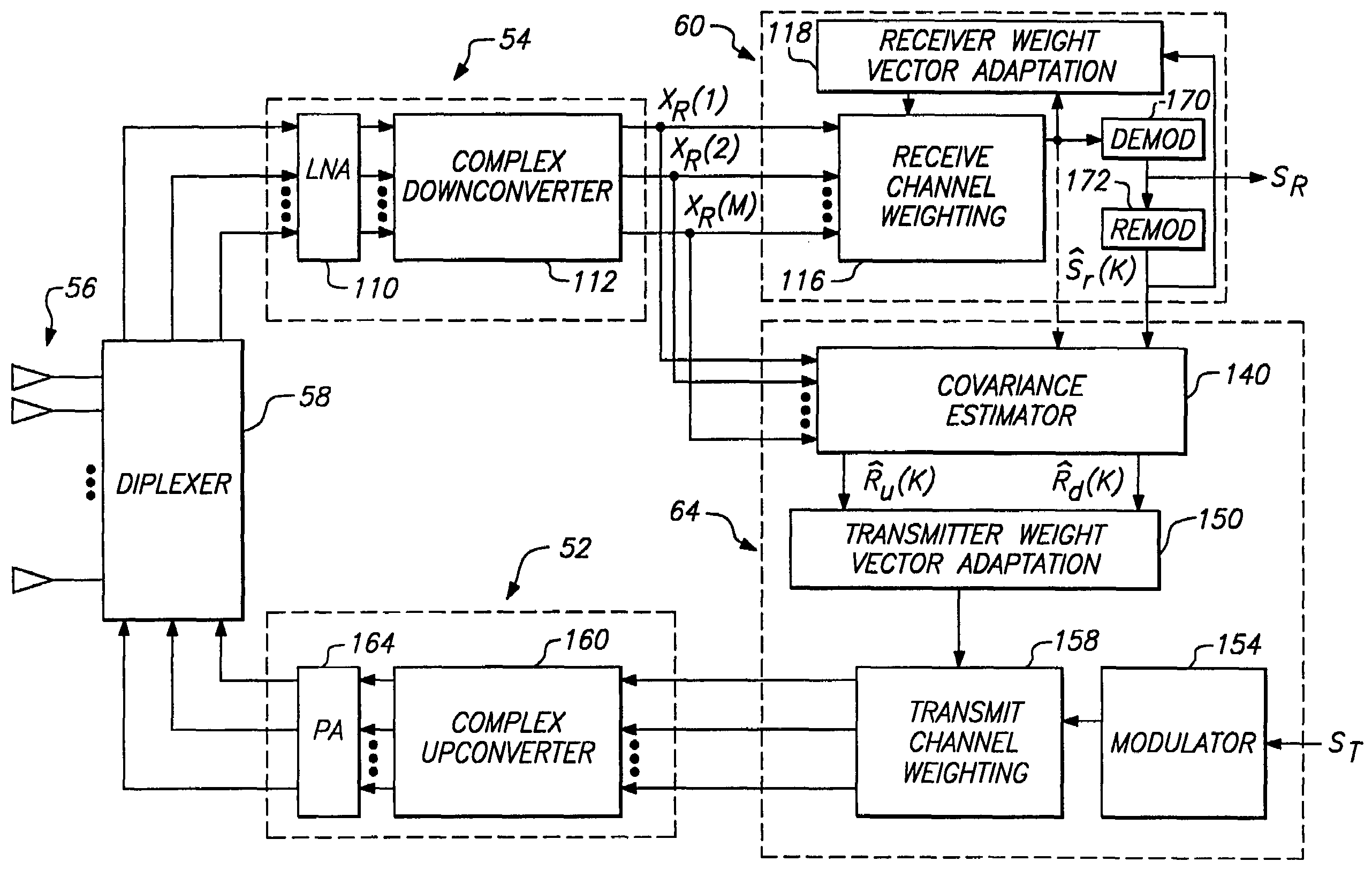
[0034]Turning now to FIG. 2A, a block diagram is shown of the physical organization of a beamforming network 50 configured to perform adaptive beam forming in accordance with the present invention. In an exemplary embodiment the beamforming network 50 is disposed within a base station of a cellular communications network, in which is included a transceiver comprised of a radio frequency (RF) transmitter 52 and an RF receiver 54.

[0035]In the embodiment of FIG. 2A, a base station antenna array 56 serves to produce independent transmit and receive antenna beams for facilitating communication with one or more mobile units (not shown). The term “receive channel vector” is employed to indicate that each antenna element within the base station antenna array 56 will form a propagation channel to a given remote user. The composite array channel may be represented as a vector having elements corresponding to each individual antenna channel. As is descri...


PUM


Abstract

A method for forming an adaptive phased array transmission beam pattern at a base station without any knowledge of array geometry or mobile feedback is described. The approach is immune to the problems which plague methods which attempt to identify received angles of arrival from the mobile and map this information to an optimum transmit beam pattern. In addition, this approach does not suffer the capacity penalty and mobile handset complexity increase associated with mobile feedback. Estimates of the receive vector propagation channels are used to estimate transmit vector channel covariance matrices which form objectives and constraints in quadratic optimization problems leading to optimum beam former solutions for the single user case, and multiple user case. The new invention in capable of substantial frequency re-use capacity improvement in a multiple user cellular network.

Description

[0001]This is a continuation of U.S. patent application Ser. No. 09 / 563,806, filed May 2, 2000 now U.S. Pat. No. 6,665,545; which is a continuation of U.S. Patent Application 08 / 491,044, filed Jun. 16, 1995, now U.S. Pat. No. 6,101,399, issued August 8, 2000; which is a continuation in part of U.S. patent application Ser. No. 08 / 394,652, filed Feb. 22, 1995, now abandoned.BACKGROUND OF THE INVENTION[0002]I. Field of the Invention[0003]The present invention relates to the formation of antenna beam patterns (beamforming), and more particularly to a technique for adaptive transmit beamforming based on the result of adaptive receive beamforming.[0004]II. Description of the Related Art[0005]Within wireless mobile communication systems, directive antennas may be employed at base station sites as a means of increasing the signal level received by each mobile user relative to the level of received signal interference. This is effected by increasing the energy radiated to a desired recipient...

Claims


Application Information

Patent Timeline
Patent Type & Authority Patents(United States)
IPC IPC(8): H04Q7/30H01Q3/26H01Q25/00H04W16/28
CPCH01Q3/2605H01Q25/00H04W16/28H01Q3/267
Inventor RALEIGH, GREGORY GENEDIGGAVI, SUHAS NAGRAJJONES, IV, VINCENT KNOWLESPAULRAJ, AROGYASWAMI JOSEPH
Owner THE BOARD OF TRUSTEES OF THE LELAND STANFORD JUNIOR UNIV
Why Eureka
Try Eureka