Method of manufacturing a magnetic head device

a manufacturing method and magnetic head technology, applied in the direction of final product manufacturing, maintaining head carrier alignment, record information storage, etc., can solve the problems of poor reliability of soldering electrical connections between terminal pads and lead connection pads, thermal damage to magnetic head sliders, deterioration of slider flying performance, etc., to achieve the effect of reliability of electrical connections

Inactive Publication Date: 2007-10-30
SAE MAGNETICS (HK) LTD
View PDF7 Cites 14 Cited by
  • Summary
  • Abstract
  • Description
  • Claims
  • Application Information

AI Technical Summary

Benefits of technology

[0011]It is therefore an object of the present invention to provide a manufacturing method and apparatus of a magnetic head device, whereby reliability of electrical connections between terminal pads of a magnetic head slider and lead connection pads of a suspension can be improved.
[0012]Another object of the present invention is to provide a manufacturing method and apparatus of a magnetic head device and a magnetic head device, whereby shape change of a magnetic head slider and damages applied to the slider during a solder reflow can be reduced.
[0014]Since the terminal pads and the connection pads are warmed by irradiating the laser beam during the preheating step or process, solder wettability of these terminal pads and connection pads can be secured without suffering thermal shape change or thermal damage to the magnetic head slider. Therefore, it is possible to improve reliability of electrical connections between the terminal pads and the lead connection pads.
[0022]Since the terminal pads and the connection pads are warmed by irradiating the laser beam by means of the preheating unit, solder wettability of these terminal pads and connection pads can be secured without suffering thermal shape change or thermal damage to the magnetic head slider. Therefore, it is possible to improve reliability of electrical connections between the terminal pads and the lead connection pads.
[0030]Fixing of the magnetic head slider with the suspension is performed only by the dummy pads connection. Since no adhesive is used, it is possible to prevent shape change in the magnetic head slider due to the difference in thermal expansion coefficients between the resin adhesive and the magnetic head slider, and thus to prevent deterioration in the flying performance of the magnetic head slider.

Problems solved by technology

However, according to the known laser reflow method described in Japanese patent publication No.2002-050017A and U.S. Pat. No. 5,828,031, when performing solder connections, no solder wettability in the terminal pads of the magnetic head slider and the lead connection pads of the suspension is secured causing poor reliability in soldering electrical connections between the terminal pads and the lead connection pads.
If preheating of the whole of HGA is performed in order to ensure solder wettability, the magnetic head slider particularly the slider with a giant magnetoresistive effect (GMR) element may suffer from thermal damage.
In the conventional HGA, also, since the magnetic head slider is fixed to the suspension by both resin adhesive and solder, during the solder reflowing process for attaching or detaching the slider to or from the suspension, shape change in the magnetic head slider due to the difference in thermal expansion coefficients between the resin adhesive and the magnetic head slider may occur causing deterioration in the flying performance of the slider.

Method used


Image

  • Method of manufacturing a magnetic head device
  • Method of manufacturing a magnetic head device
  • Method of manufacturing a magnetic head device

Examples


Embodiment Construction

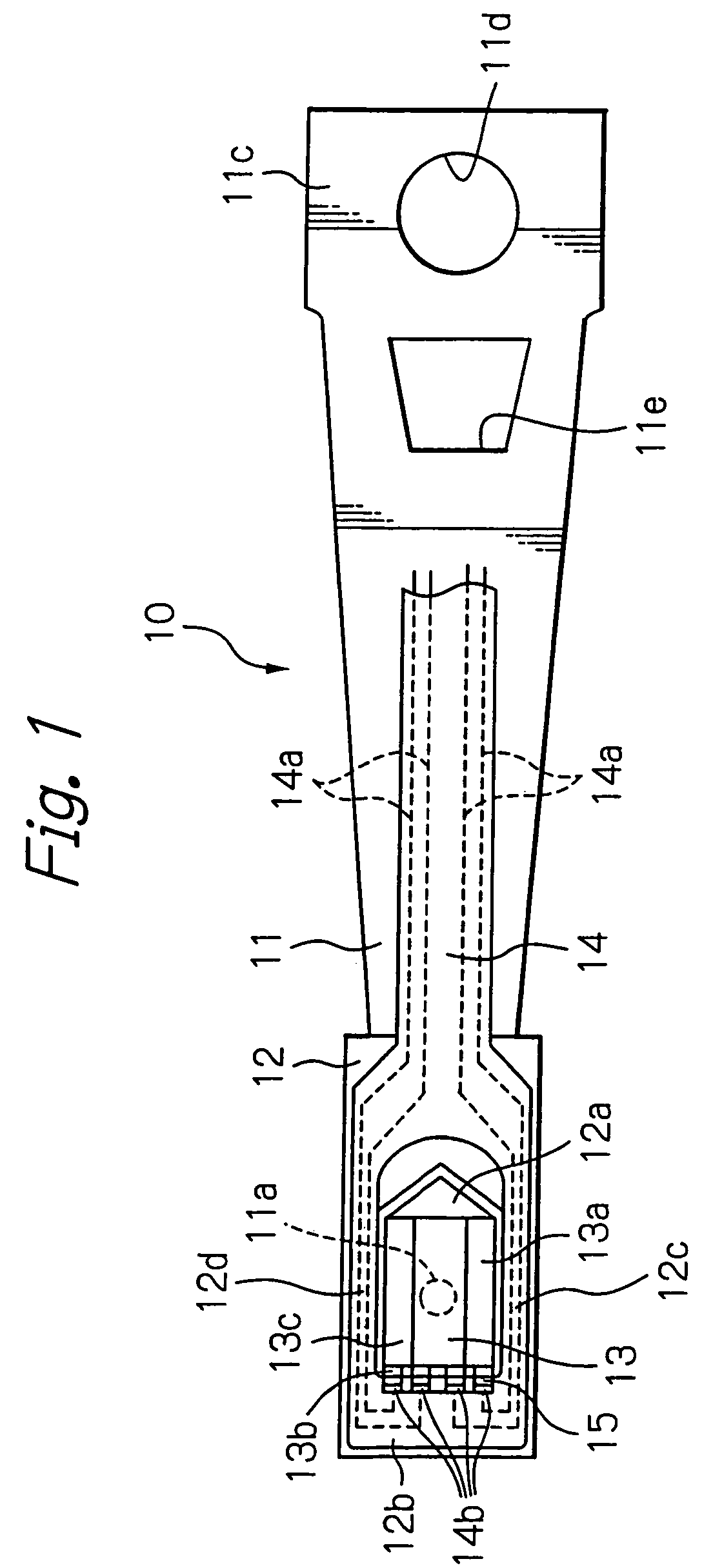
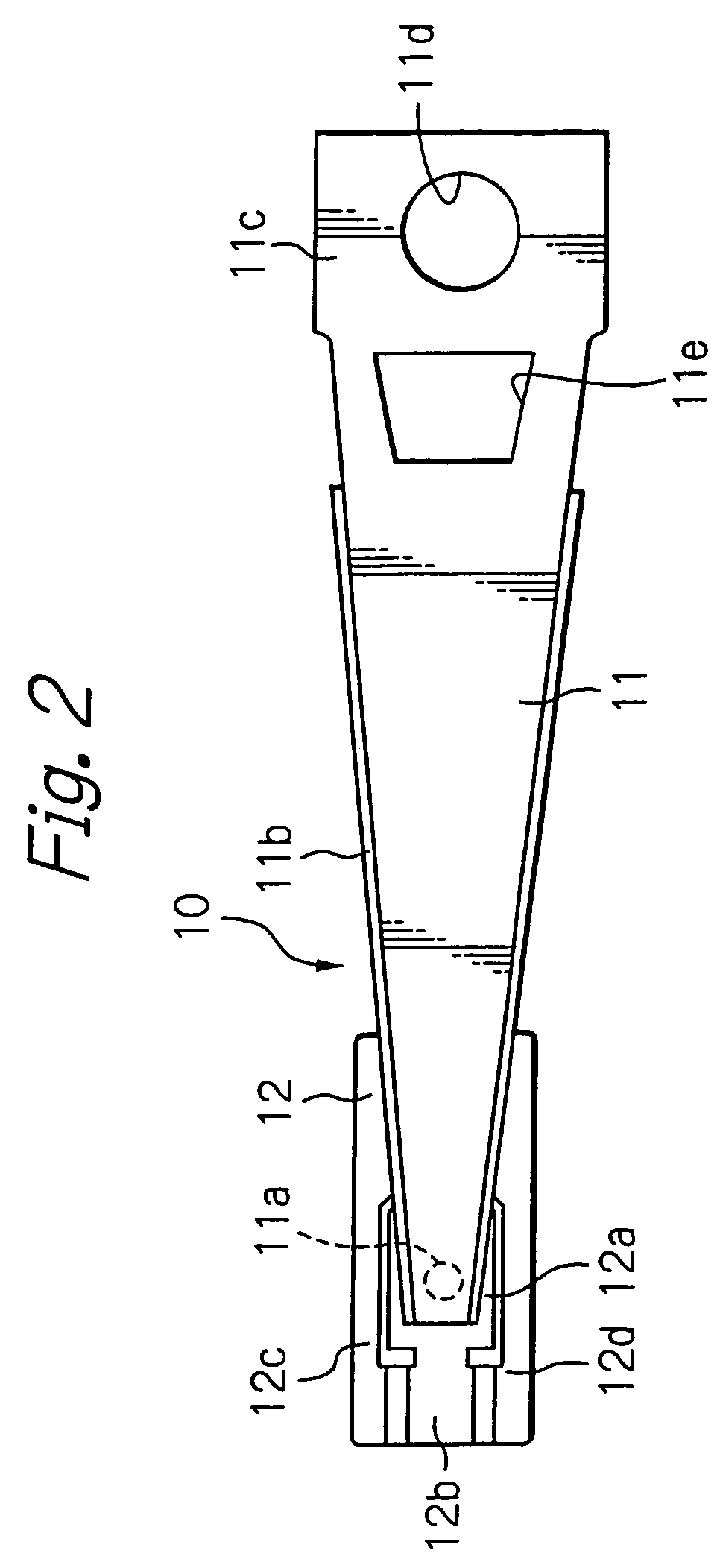
[0059]FIG. 1 illustrates an HGA seen from a slider-mounting side as a preferred embodiment of a magnetic head device according to the present invention, FIG. 2 illustrates the HGA shown in FIG. 1 seen from the opposite side of the slider-mounting side, and FIG. 3 illustrates an enlarged top end section of the HGA shown in FIGS. 1 and 2.

[0060]As shown in these figures, the HGA has a suspension 10 mainly constituted by a load beam 11 with a relatively high stiffness and a resilient flexure 12, a magnetic head slider 13 fixed on the suspension 10, and a lead conductor member 14 formed on or fixed to the suspension 10.

[0061]The load beam 11 has a protrusion or dimple 11a for applying a load to the magnetic head slider 13. This dimple 11a is positioned on the longitudinal center axis line near a free end section or top end section of the load beam 11. As shown in FIGS. 2 and 3, the load beam 11 also has bent sections or ribs 11b at both side edges for increasing stiffness of the correspo...


PUM

PropertyMeasurementUnit
temperatureaaaaaaaaaa
diameteraaaaaaaaaa
sizesaaaaaaaaaa

Abstract

A manufacturing method of a magnetic head device includes a preheating step of irradiating a laser beam to terminal pads of a magnetic head slider and to connection pads of a lead conductor member that is to be electrically connected to the magnetic head slider, a supply step of supplying conductive metal material for connecting the terminal pads and the connection pads during or after the preheating step, and a heating step of performing molten-metal connections between the terminal pads and the connection pads by irradiating a laser beam to the conductive metal material.

Description

BACKGROUND OF THE INVENTION[0001]1. Field of the Invention[0002]The present invention relates to a manufacturing method of a magnetic head device, to a manufacturing apparatus of a magnetic head device and to a magnetic head device. Particularly, the present invention relates to a manufacturing method and apparatus of a magnetic head device with a flying-type magnetic head slider with at least one magnetic write head element and / or at least one magnetic read head element and / or a micro-actuator, and to the magnetic head device.[0003]2. Description of the Related Art[0004]There are three practical variations of a flying-type magnetic head device in a magnetic disk drive apparatus, that is, a head gimbal assembly (HGA) with a suspension and a magnetic head slider attached on the suspension, a head arm assembly (HAA) with a support arm and at least one HGA attached to the support arm, and a head stack assembly (HSA) with a plurality of HAAs stacked on each other.[0005]A typical HGA has...

Claims


Application Information

Patent Timeline
Patent Type & Authority Patents(United States)
IPC IPC(8): G11B5/48B23K26/20B23K1/20G11B5/60G11B21/21H05K3/34
CPCG11B5/4853G11B5/486H05K3/3442H05K3/3494H05K2201/09781H05K2203/041Y10T29/4903H05K2203/111H01L2224/742Y10T29/49027Y10T29/49144Y10T29/49025Y10T29/49149H05K2203/107Y02P70/50
Inventor YAMAGUCHI, SATOSHI
Owner SAE MAGNETICS (HK) LTD
Why Eureka
Try Eureka