Hydraulic device

a technology of hydraulic devices and water pipes, applied in the direction of fluid pressure control, process and machine control, instruments, etc., can solve the problems of uncontrollable wind, difficult, if not impossible, extreme disposal of radioactive waste, etc., and achieve the effect of being economical and environmentally friendly

Inactive Publication Date: 2007-10-30
WU CHING CHUAN
View PDF5 Cites 2 Cited by
  • Summary
  • Abstract
  • Description
  • Claims
  • Application Information

AI Technical Summary

Benefits of technology

[0007]The primary purpose of the present invention is to provides a hydraulic device for the generation of hydroelectricity and for irrigation, which is both inexpensive and environmentally friendly.

Problems solved by technology

Clean and efficient power generation is the most critical challenge in the new millennium as the earth's natural resources are gradually depleted.
Nuclear power generation, on the other hand, is notorious about its radioactive waste whose disposal is extremely difficult, if not impossible, to solve.
Wind power is unlimited to harness but the direction and strength of the natural wind are not human-controllable, and the production cost is relatively high compared to the conventional power generation methods.
However, the production cost is rather high as usually a dam has to be built and maintained.

Method used


Image

  • Hydraulic device
  • Hydraulic device
  • Hydraulic device

Examples


Embodiment Construction

[0014]The following descriptions are of exemplary embodiments only, and are not intended to limit the scope, applicability or configuration of the invention in any way. Rather, the following description provides a convenient illustration for implementing exemplary embodiments of the invention. Various changes to the described embodiments may be made in the function and arrangement of the elements described without departing from the scope of the invention as set forth in the appended claims.

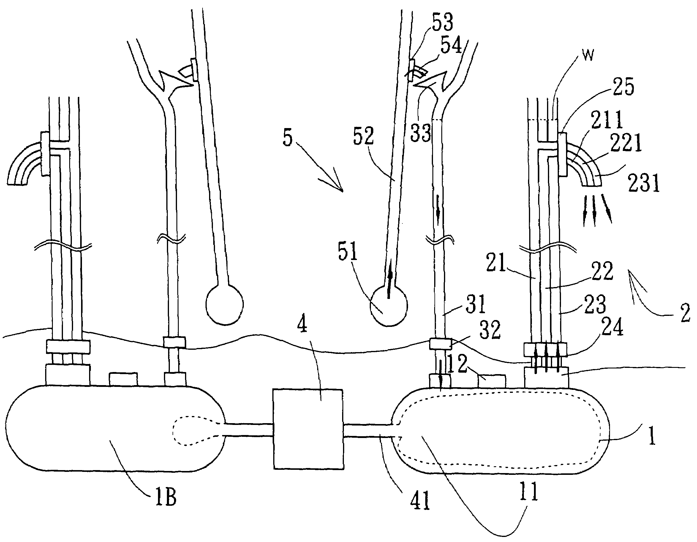
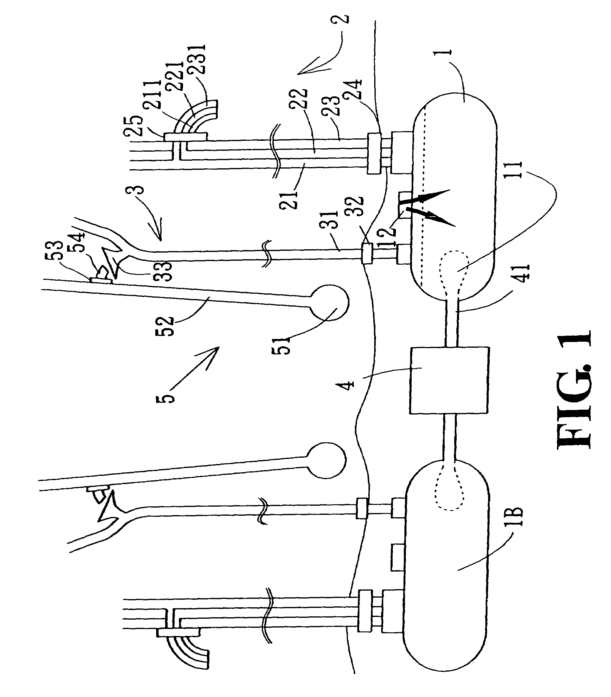
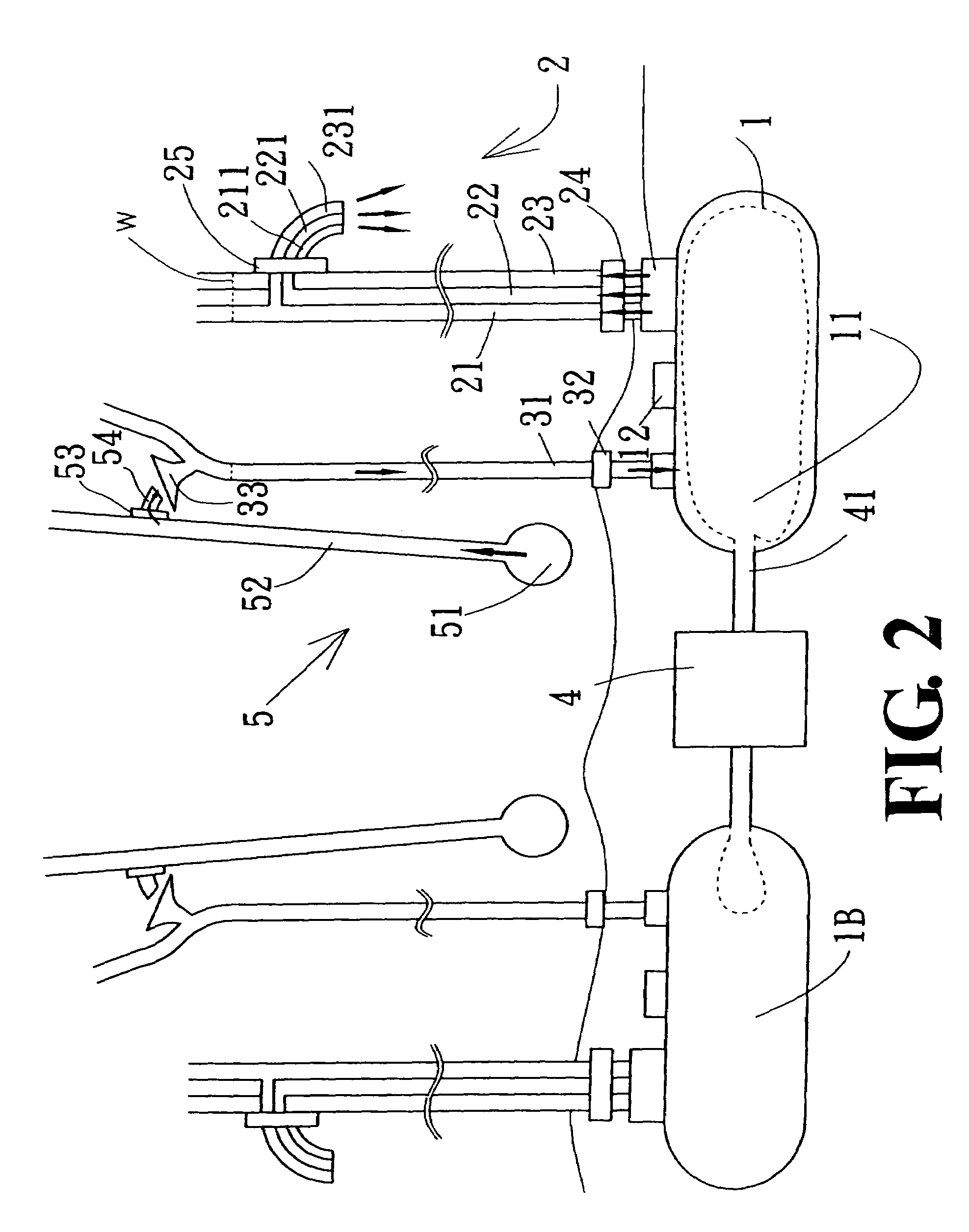
[0015]As shown in FIG. 1, an embodiment of the present invention mainly contains an air compressor 4 and two identical assemblies. Each assembly contains a reservoir 1, an outlet pipe group 2, an inlet pipe 31, and a pumper 5. Inside the reservoir 1, there is an airbag 11 connecting to and receiving air from the air compressor 4 via an air pipe 41. The outlet pipe group 2 and the inlet pipe 31 are provided substantially perpendicularly on a top side of the reservoir 1. Also on the top side of the...


PUM


Abstract

A hydraulic device is provided herein. The hydraulic device mainly contains a reservoir having an airbag inside. The reservoir is provided with an inlet pipe and a plurality of outlet pipes, both extended from a top side of the reservoir. The inlet pipe receives water from a pumper and fills the reservoir via a back-pressure valve. The airbag expands by the air driven by an air compressor to force water from the reservoir into the outlet pipes. When the water level of the inlet pipe is higher than that of the outlet pipes, due to the siphon principle, water will continuously flows from the inlet pipe, through the vacuumed reservoir, into and then out of the outlet pipes. The water poured out of the outlet pipes can be utilized for hydroelectricity or irrigation.

Description

BACKGROUND OF THE INVENTION[0001](a) Technical Field of the Invention[0002]The present invention generally relates to hydraulic devices, and more particularly to a hydraulic device based on the siphon principle for hydroelectricity and irrigation.[0003](b) Description of the Prior Art[0004]Clean and efficient power generation is the most critical challenge in the new millennium as the earth's natural resources are gradually depleted. Thermal power generation by burning fossil fuel is well known to be one of the major causes to acid rain, greenhouse effect, all sorts of air and water pollutions, and damage to the ozone layer, just to name a few. Nuclear power generation, on the other hand, is notorious about its radioactive waste whose disposal is extremely difficult, if not impossible, to solve.[0005]Wind and hydraulic power generations are the two most environmentally friendly approaches. Wind power is unlimited to harness but the direction and strength of the natural wind are not ...

Claims


Application Information

Patent Timeline
Patent Type & Authority Patents(United States)
IPC IPC(8): G05D16/00B67D7/72
CPCF03B17/00F03D9/001Y02E10/72Y02E10/20F03D9/28Y10T137/3127Y10T137/4673Y10T137/469
Inventor WU, CHING-CHUAN
Owner WU CHING CHUAN
Why Eureka
Try Eureka