Steerable drilling apparatus having a differential displacement side-force exerting mechanism

a drilling apparatus and differential displacement technology, applied in drilling pipes, drilling rods, directional drilling, etc., can solve problems such as substantial pressure drop across the bi

Inactive Publication Date: 2007-10-30
SCIENCE DRILLING INTERNATIONAL INC
View PDF30 Cites 37 Cited by
  • Summary
  • Abstract
  • Description
  • Claims
  • Application Information

AI Technical Summary

Benefits of technology

[0014]An important object of the present invention is to provide a simpler and less-costly apparatus for steerable rotary drilling that overcomes shortcomings of prior art apparatus, and is useful in boreholes having any directional path, from vertical to horizontal and beyond, and enables its effective direction control force to be set while the drill string is within the borehole.

Problems solved by technology

When such pumps are operating, there will be a substantial pressure drop across the bit resulting from the mud flow through the bit.

Method used


Image

  • Steerable drilling apparatus having a differential displacement side-force exerting mechanism
  • Steerable drilling apparatus having a differential displacement side-force exerting mechanism
  • Steerable drilling apparatus having a differential displacement side-force exerting mechanism

Examples


Embodiment Construction

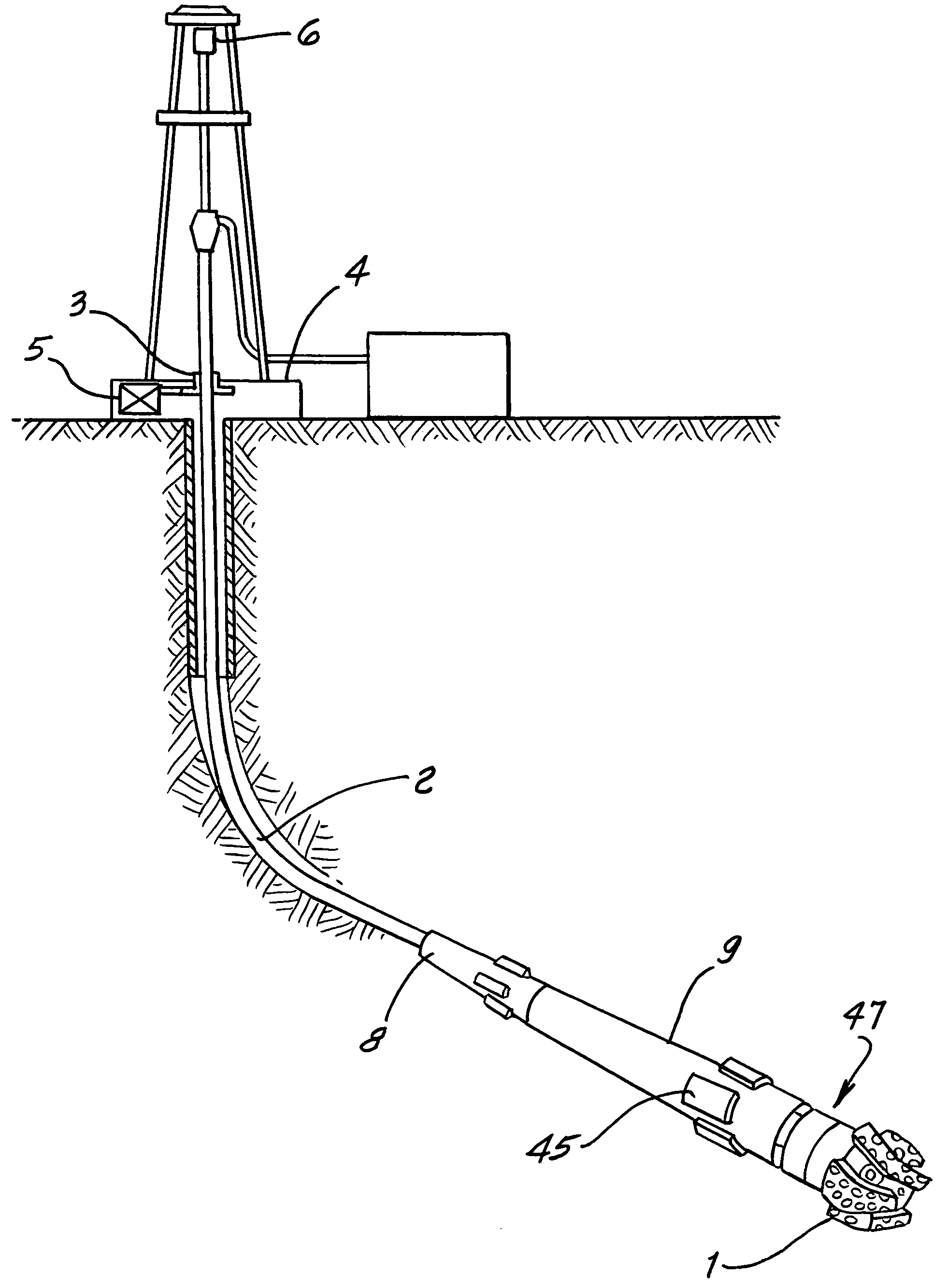
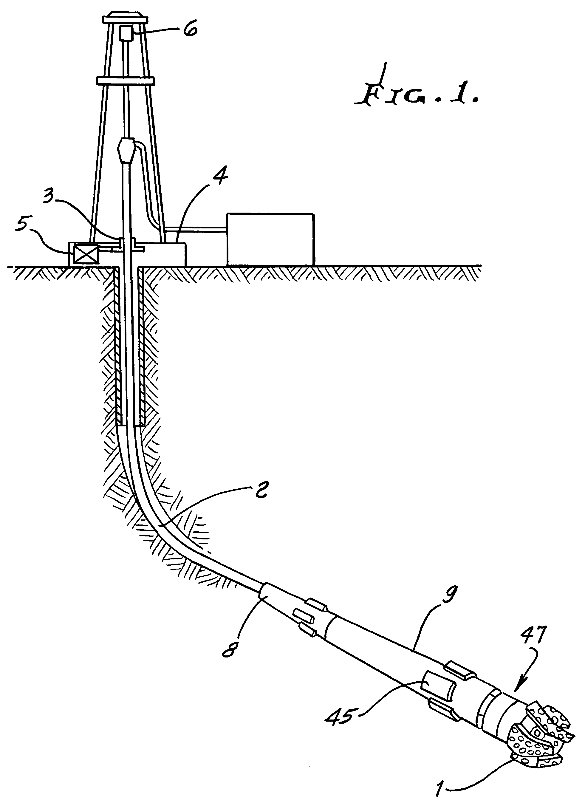
[0045]FIG. 1 shows diagrammatically a typical rotary drilling installation of a kind in which the present invention may be used. The bottom hole assembly includes a drill bit 1 and is connected to the lower end of drill string 2 which is rotatably driven from the surface by a rotary table 3 on a drilling platform 4. The rotary table is driven by a drive motor 5. Raising and lowering of the drill string, and application of weight-on-bit, is under the control of draw works indicated diagrammatically at 6.

[0046]The bottom hole assembly includes a bearing section 8 for attachment to the drill string 2 that permits rotary motion between the drill string 2 and the steerable section 9. The outer surface of the steerable section 9 may be held in a fixed non-rotational direction or it may be allowed to rotate slowly as the drill string penetrates into the earth. Internal to the steerable section, a rotary element connects the drill string 2 to the drill bit 1. Radially-extensible side-force ...


PUM


Abstract

An apparatus for steerable rotary drilling of a borehole having a wall in the earth comprising a mandrel having a central opening there through for the passage of drilling fluids. The mandrel having a lower connection for operatively connecting to a drill bit structure and an upper connection for operatively connecting to a drill string above said apparatus. The mandrel further having an intermediate portion, an outer housing surrounding longitudinal extent of the mandrel intermediate portion, a differential displacement drive within the outer housing, one or more pairs of radially-extensible, opposed side-force exerting elements controlled by the differential displacement drive to provide for side force exertion against the borehole wall.

Description

BACKGROUND OF THE INVENTION[0001]This invention relates generally to controlling of the direction of drilling a borehole in the earth, for causing that borehole to traverse a desired path within the earth.[0002]Early apparatus and methods used for this purpose employed a device called a whipstock that was lowered into a borehole and oriented to the direction of desired borehole divergence from its initial path. This apparatus had a tapered portion that would force the drill bit to diverge in the oriented direction. Later apparatus and methods were developed that used a down-hole motor, driven by drilling-mud flow or other means. Such motors are typically mounted to the lower end of a bent subassembly such that the longitudinal axis of the motor, and the drilling bit at its lower end, are at a slight angle to the direction of the drill string above the bent subassembly. When it is desired to drill in a generally straight path, the motor may be not activated, if desired, and drill str...

Claims


Application Information

Patent Timeline
Patent Type & Authority Patents(United States)
IPC IPC(8): E21B7/08E21B7/06
CPCE21B7/068E21B7/06
Inventor VAN STEENWYK, DONALD H.TEYS, RAYMOND W.
Owner SCIENCE DRILLING INTERNATIONAL INC
Why Eureka
Try Eureka