Motor generator

a motor generator and motor technology, applied in the direction of synchronous generators with multiple outputs, magnetic circuit rotating parts, magnetic circuit shapes/forms/construction, etc., can solve the problems of increasing the space for motor generators, increasing costs, and increasing the size of motor generators, so as to reduce installation space and reduce costs

Active Publication Date: 2007-10-30
PANASONIC CORP
View PDF27 Cites 21 Cited by
  • Summary
  • Abstract
  • Description
  • Claims
  • Application Information

AI Technical Summary

Benefits of technology

[0011]In view of the aforementioned problems, it is an object of the present invention to provide a motor generator formed by combining a plurality of types of the motor generator of field winding type using permanent magnets such that a plurality of electric powers can be input to or output from different sources independently at a reduced cost while reducing the installation space, and the distribution of the electric power can be arbitrarily designed.
[0013]According to the above aspect of the invention, the motor generator has a simple structure of magnetic field type using the permanent magnets, and formed by providing windings around the respective stator teeth by the number smaller than that of the permanent magnets. This makes it possible to reduce the space and cost. The stator teeth are formed of the first stator teeth section and the second stator teeth section such that a plurality of electric powers may be input / output with respect to the respective windings of the first and second stator teeth sections independently. Further the respective numbers of the stator teeth of the first and second stator teeth sections are arbitrarily selected, resulting in freedom in designing distribution of the electric power to be input / output.
[0015]According to the above aspect of the invention, the motor generator has a simple structure of magnetic field type using the permanent magnets, and formed by providing windings on the respective stator teeth by the number smaller than that of the permanent magnets. This makes it possible to reduce the space and cost. Electric power may be input / output with respect to each of the windings of the respective secondary stator teeth sections in the plurality of stator teeth groups, independently. The invention allows the secondary stator teeth section to be arbitrarily determined, resulting in freedom in designing distribution of the electric power.
[0017]As the motor generator is formed by combining the aforementioned two aspects of the invention, electric power may be input / output via three or more channels in addition to the effects as described above, which allows the distribution of electric power to be arbitrarily designed.
[0019]The motor generator according to this aspect of the invention has a simple structure of magnetic field type using the permanent magnets, and formed by providing windings on the respective stator teeth by the number smaller than that of the permanent magnets. This makes it possible to reduce the space and cost. The thickness or diameter of the unit may be changed so as to input / output electric power through a plurality of channels while arbitrarily designing distribution of the electric power.

Problems solved by technology

This may cause increase not only in space to accommodate those units but also in cost.
In the case where the motor generator of the field winding type having two windings is employed, and one of those windings is wound for driving the vehicle, the size of the motor generator becomes so large that it cannot be mounted on the vehicle.
Additionally, it is difficult to control the aforementioned windings simultaneously because of the field winding type.

Method used


Image

  • Motor generator
  • Motor generator
  • Motor generator

Examples


first embodiment

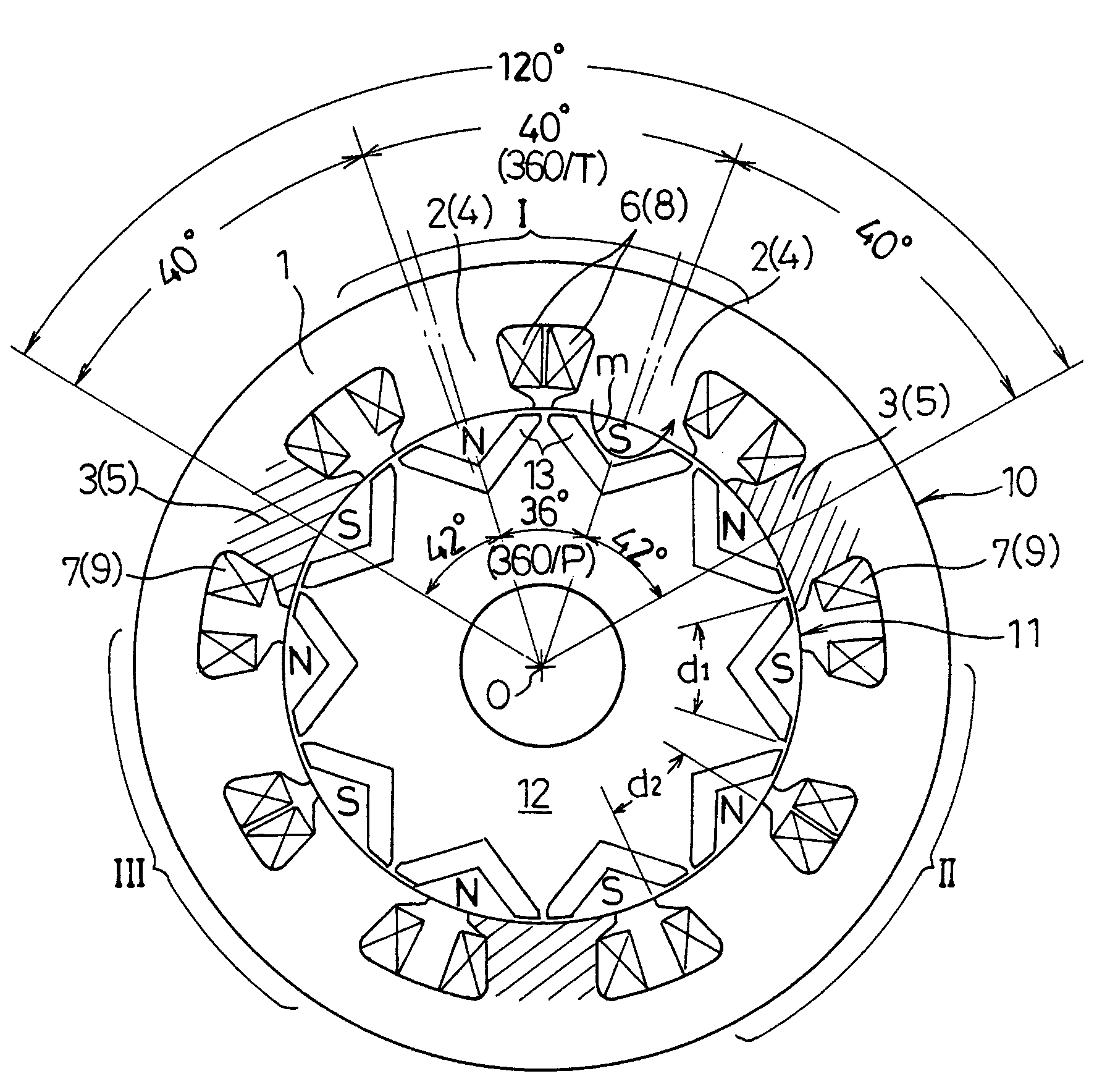
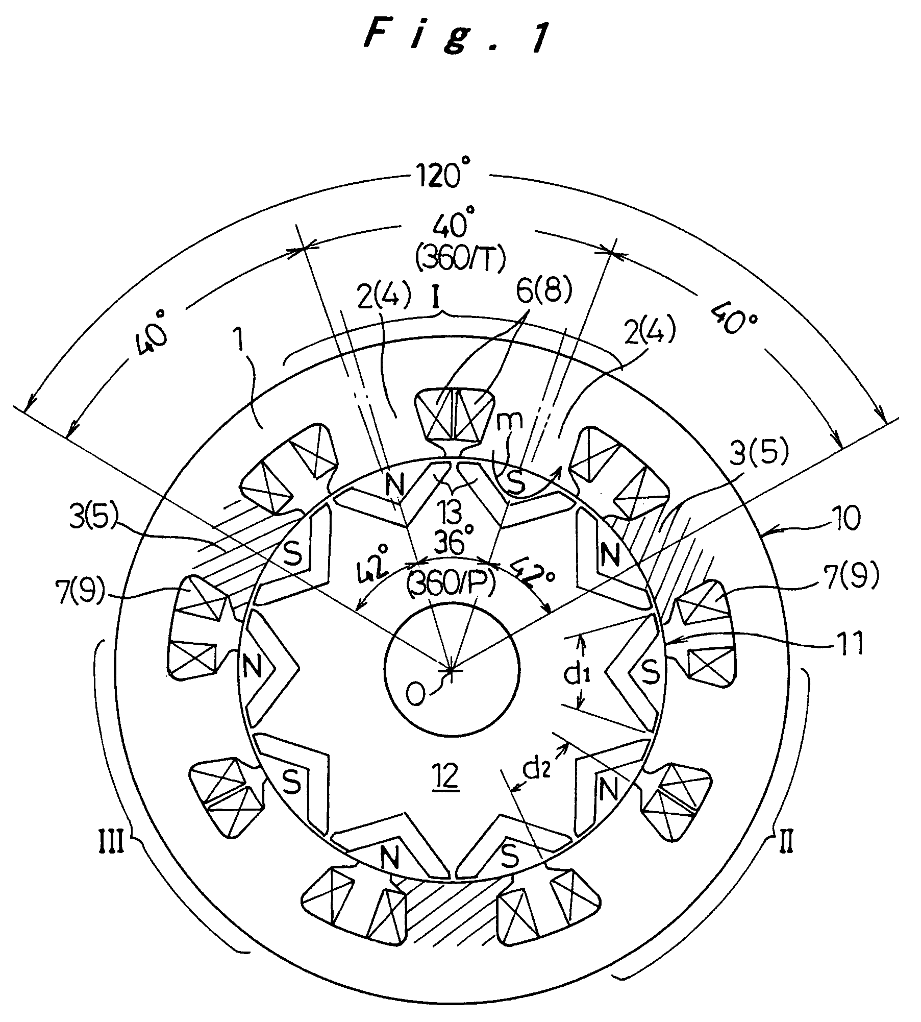
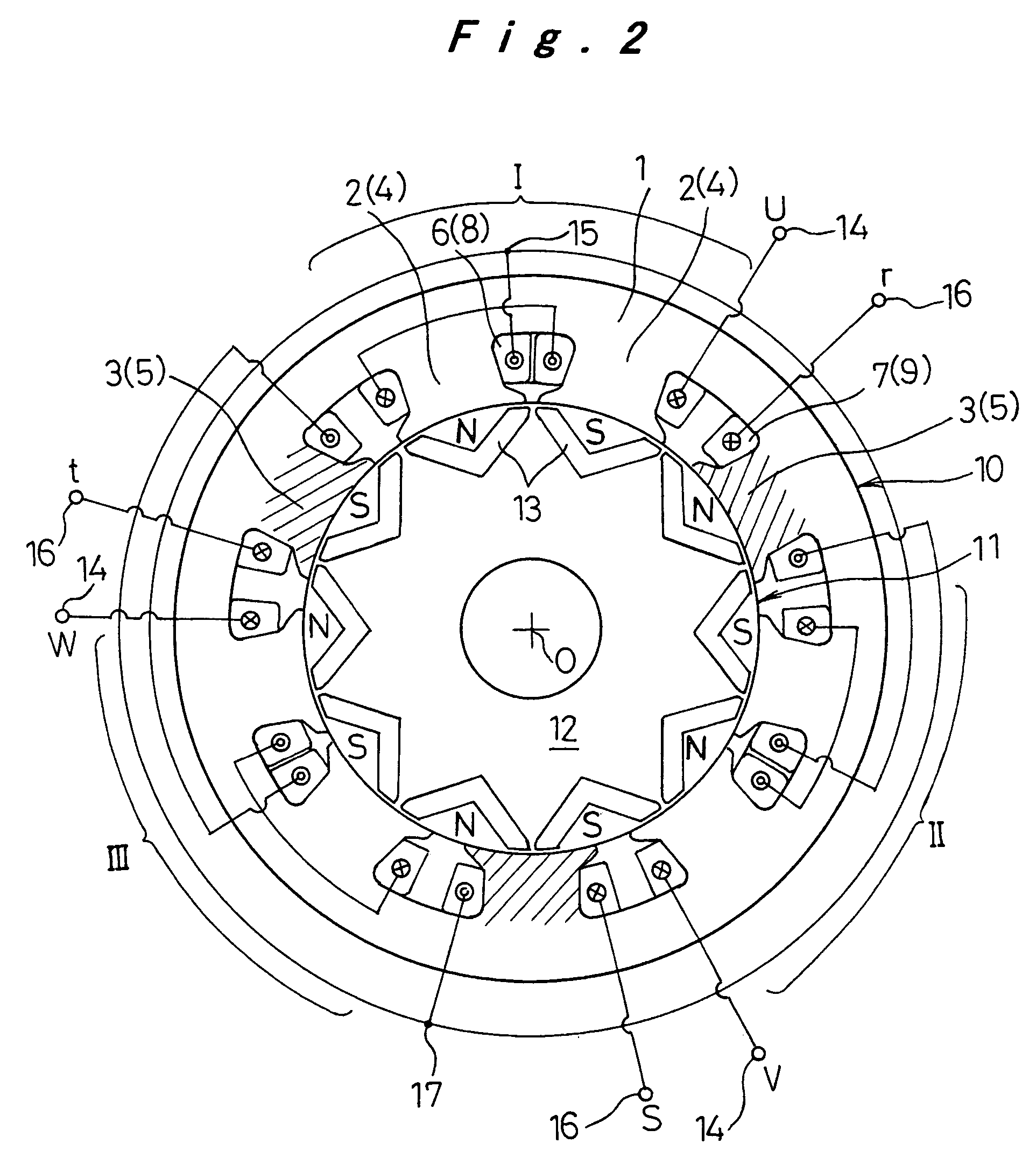
[0051]A first embodiment of the motor generator according to the invention will be described with reference to FIGS. 1 to 6. FIG. 1 is a vertical sectional view of the motor generator of the invention with respect to the rotating axis. FIG. 2 is a connecting diagram of the winding. Referring to FIG. 1, a stator core 1 formed by stacking electromagnetic steel plates is provided with a plurality of stator teeth 2 that constitute a first stator teeth section 4, and a plurality of stator teeth 3 (shaded to be distinguished from the stator teeth 2) that constitute a second stator teeth section 5. A winding 6 that constitutes a first winding section 8 is wound around the stator teeth 2, and a winding 7 that constitutes a second winding section 9 is wound around the stator teeth 3 so as to form a stator 10.

[0052]Meanwhile a rotor 11 is formed by embedding a plurality (even number) of permanent magnets 13 at uniform intervals in the rotor core 12 formed as the stacked electromagnetic plates...

second embodiment

[0068]A second embodiment of the invention will be described with reference to FIGS. 7A and 7B. The structural elements identical to those described in the first embodiment will be designated by the same reference numerals, and the description thereof will be omitted and the following descriptions focus mainly on the points of difference from the preceding embodiment.

[0069]In the previous embodiment, the rotor 11 is of magnet type formed by embedding permanent magnets 13 in the rotor core 12. In this embodiment, the rotor 11 is formed by stacking magnet type rotor portions 21 and reluctance type rotor portions 22 in the axial direction as shown in FIG. 7A. The magnet type rotor portion 21 is formed by embedding the permanent magnets 13 in the rotor core 12. The reluctance type rotor portion 22, as shown in FIG. 7B, has stator teeth 25 by the number equal to that of the permanent magnets 13 by forming recess portions 24 on the outer periphery of the rotor core 23 at equal intervals.

[...

third embodiment

[0071]A third embodiment of the invention will be described with reference to FIG. 8. The motor generator in the previous embodiment has three pairs in total, that is, two pairs in the first stator teeth section 4, and one pair in the second stator teeth section 5. The motor generator in this embodiment includes five pairs in total, that is, three pairs in the first stator teeth section 4, and two pairs in the second stator teeth section 5, fifteen stator teeth in total, and sixteen poles (not shown) of the permanent magnets 13. In the case where the second stator teeth section 5 has more than one pair, the pitch of the stator teeth 2 of the first stator teeth section 4 is set to 24° (360 / T), and the pitch of the stator teeth 3 of the second stator teeth section 5 is set to 22.5° (360 / P). The length of the leg 18 that extends toward both sides in the circumferential direction is adjusted at the distal ends of each of the stator teeth 2 and 3 such that the open slot angle os1 between...


PUM


Abstract

A motor generator is provided with a stator having a winding around each of a plurality of stator teeth, and a rotor having a plurality of permanent magnets by the number larger than that of the stator teeth, arranged in the circumferential direction at equal intervals. The stator teeth are formed of a first stator teeth section including a plurality of stator teeth groups I, II, and III each including the adjacent stator teeth around which a winding to which the same phase voltage is applied is wound and in which winding directions of the stator teeth are opposite to each other, and a second stator teeth section including a stator teeth having a winding wound therearound and being placed among stator teeth groups of different phases such that electric power is independently input and output with respect to the first and second winding sections. This makes it possible to reduce the space and the cost while inputting / outputting the electric power through different channels and allowing arbitrary design of the electric power distribution.

Description

[0001]The present disclosure relates to subject matter contained in priority Japanese Patent Application No. 2003-303068, filed on Aug. 27, 2003, the contents of which is herein expressly incorporated by reference in its entirety.BACKGROUND OF THE INVENTION[0002]1. Field of the Invention[0003]The present invention relates to a motor generator, and more particularly, to a motor generator that can be applied to an electric vehicle such as a pure electric vehicle (PEV), a hybrid electric vehicle (HEV) and a fuel cell electric vehicle (FCEV), a high power aerogenerator, and a generator for an internal combustion engine.[0004]2. Description of the Related Art[0005]A hybrid electric vehicle provided with a drive system including an internal combustion engine and an electric motor has two types of batteries, that is, a high voltage battery for driving the electric motor and a low voltage battery for driving an accessory of the vehicle such as a lamp unit and audio equipment. The high volta...

Claims


Application Information

Patent Timeline
Patent Type & Authority Patents(United States)
IPC IPC(8): H02K1/06F03D9/00B60L50/16H02K1/14H02K1/27H02K3/20H02K3/28H02K16/04H02K21/02H02K21/04H02K21/16H02K21/48H02K29/03
CPCH02K21/046H02K21/16Y02E10/72B60L2220/14B60L2220/16B60L2220/50B60L50/16Y02T10/64Y02T10/7072Y02T10/70
Inventor TAMAKI, SATOSHIKONDO, YASUHIRONAGAKI, TOSHIKAZUNAKATA, HIDEKI
Owner PANASONIC CORP
Why Eureka
Try Eureka