Stator core

a technology of stator cores and cores, which is applied in the direction of magnetic circuits characterised by magnetic materials, magnetic circuit shapes/forms/construction, magnetic circuit rotating parts, etc., can solve the problems of low thermal conductivity, inability to cool, and loss of iron, so as to improve conduction transfer and high thermal conductivity , the effect of high thermal conductivity

Active Publication Date: 2007-10-30
ROLLS ROYCE PLC
View PDF8 Cites 33 Cited by
  • Summary
  • Abstract
  • Description
  • Claims
  • Application Information

AI Technical Summary

Benefits of technology

[0013]Possibly, the components of high thermal conductivity have face surfaces to improve conduction transfer with the low loss stator iron assembly.
[0014]Possibly, there is a high th...

Problems solved by technology

These losses are due to electrical resistance in the windings and losses in the iron.
These losses take the form of thermal energy.
Alternating magnetic flux in the core causes iron losses (eddy currents and hysteresis) which causes heating.
Inevitably low electrical conductivity means low thermal conductivity which thus inhibits cooling.
Unfortunately such materials have lower thermal conductivity properties than i...

Method used


Image

  • Stator core
  • Stator core
  • Stator core

Examples


Embodiment Construction

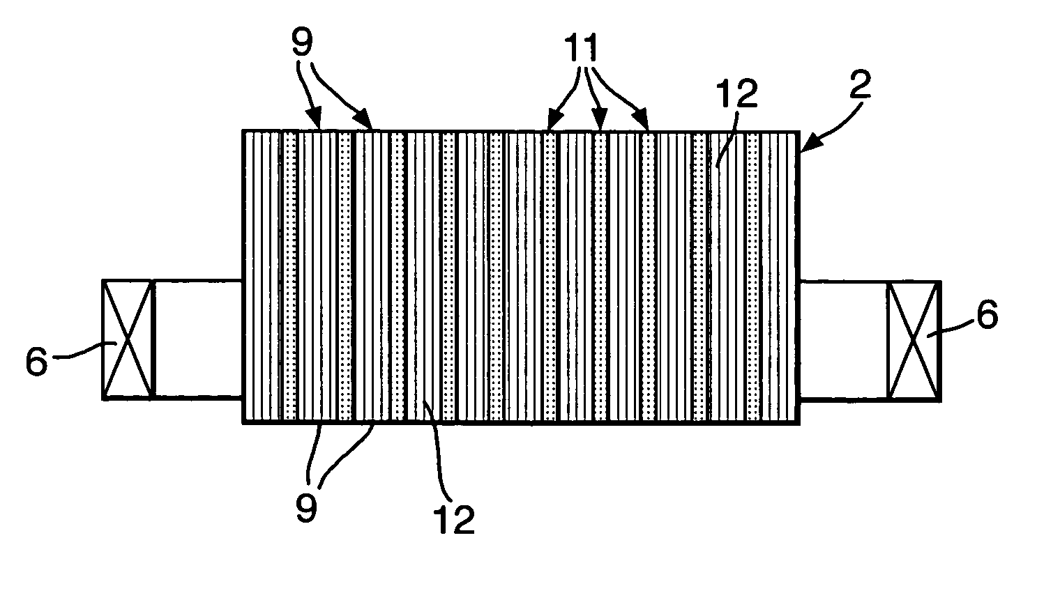
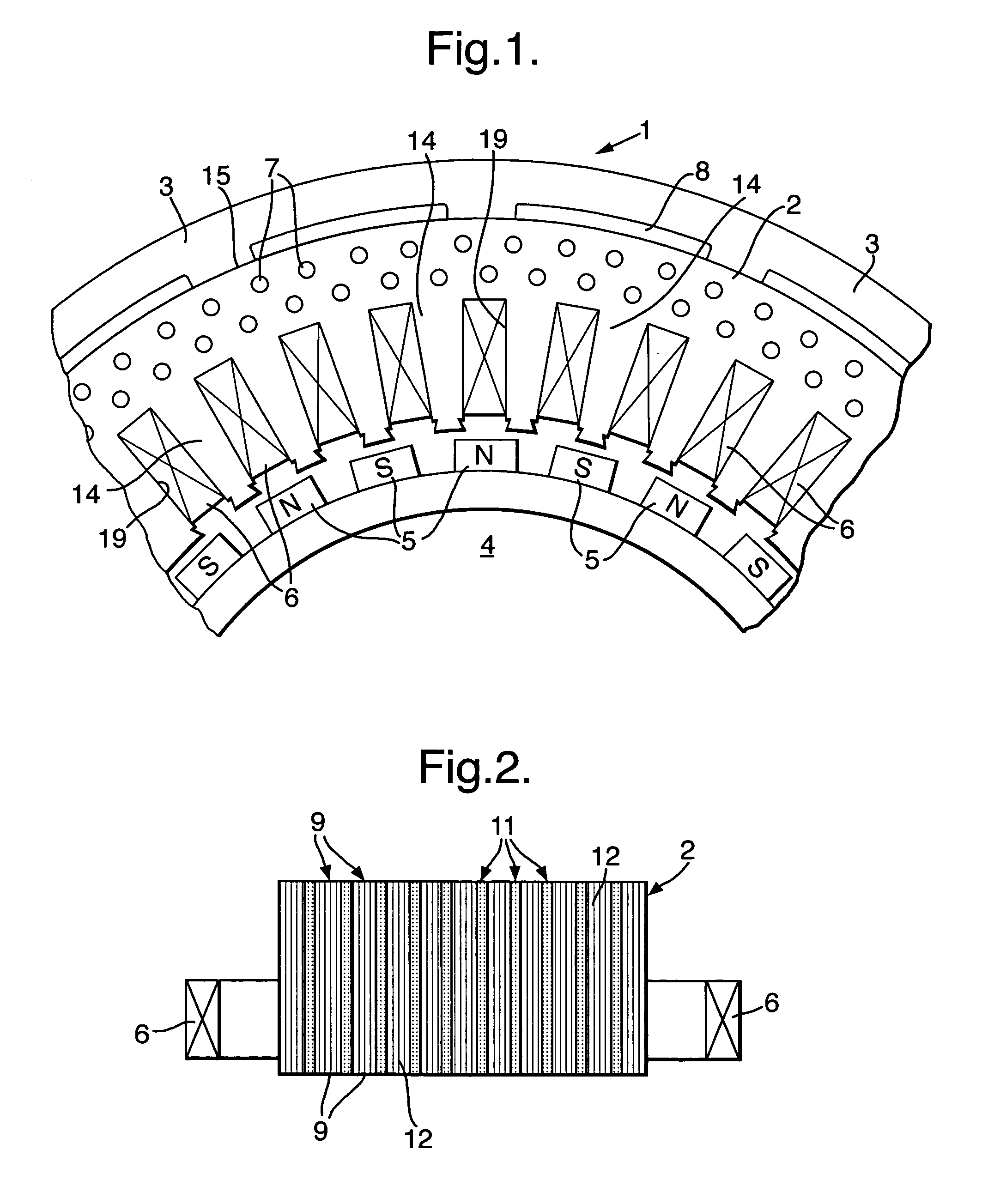
[0019]As indicated in FIG. 1 the stator core 2 has windings 6 in slots 19 which face inwards towards a rotor 4 which presents permanent magnets 5. Nevertheless, it will be appreciated that a rotor 4 could take the windings for electro-magnetic action and the stator have the permanent magnets or both could be provided with windings for electrical machine operation. The present invention in particular relates to means of improving heat conduction from these windings 6 and more particularly through the core teeth between these windings 6 for greater temperature control. FIG. 2 provides a cross-sectional view through the core 2 in a direction perpendicular to the plane of the drawing in FIG. 1.

[0020]The core 2 is formed as an assembly from a number of laminations 9 of low loss stator iron having high electrical resistivity and a lesser number of laminations 11 of high thermal conductivity material. By implication the high thermal conductivity material will generally not be capable of pr...


PUM


Abstract

A stator core 2 comprises laminations (9) of low loss stator iron forming a body of magnetic nature and lamination components (11) of high thermal conductivity material regularly arranged within that body. The high thermal conductivity components (11) increasing the effective radial thermal conductivity rate of the core 2 whereby temperature gradients are reduced in comparison with previous stator cores. Thus, there is a reduction in operational temperature of the electrical insulation on the stator windings.

Description

FIELD OF THE INVENTION[0001]The present invention relates to stator cores and more particularly to stator cores used in electrical machines with electro-magnetic windings of a compact size.BACKGROUND OF THE INVENTION[0002]Inherently, heat is generated by losses in the windings and the stator core of an electrical machine such as a motor or generator. These losses are due to electrical resistance in the windings and losses in the iron. These losses take the form of thermal energy. This thermal energy must be removed by thermal conduction out of the stator core. An example of an electrical machine is a permanent magnet electrical machine which takes the form of a stator core held in a frame with inwardly facing windings which interact in operation with a rotor core which normally carries permanent magnets. Thus, with electrical current sequentially passed through the windings, the rotor can be driven and turned. Alternatively, if the rotor is driven by other means then electrical curr...

Claims


Application Information

Patent Timeline
IPC IPC(8): H02K1/00H02K1/02H02K1/20H02K5/20H02K9/00
CPCH02K1/02H02K5/20H02K1/20H02K9/00H02K5/207
Inventor MITCHAM, ALAN JRAZZELL, ANTHONY G
Owner ROLLS ROYCE PLC
Why Eureka
Try Eureka