
Cryogenic NMR probe

a cryogenic nmr and probe technology, applied in the field of nmr probes, can solve the problems of increasing the thermal load of the heat exchanger, temperature rise, magnetic field disturbance, etc., and achieves the effects of improving the thermal regulation of the cold head, improving the thermal stability of the cold probe components, and robust and reliable cryo-pumping

Inactive Publication Date: 2007-10-30
AGILENT TECH INC
View PDF5 Cites 23 Cited by
  • Summary
  • Abstract
  • Description
  • Claims
  • Application Information

AI Technical Summary

Benefits of technology

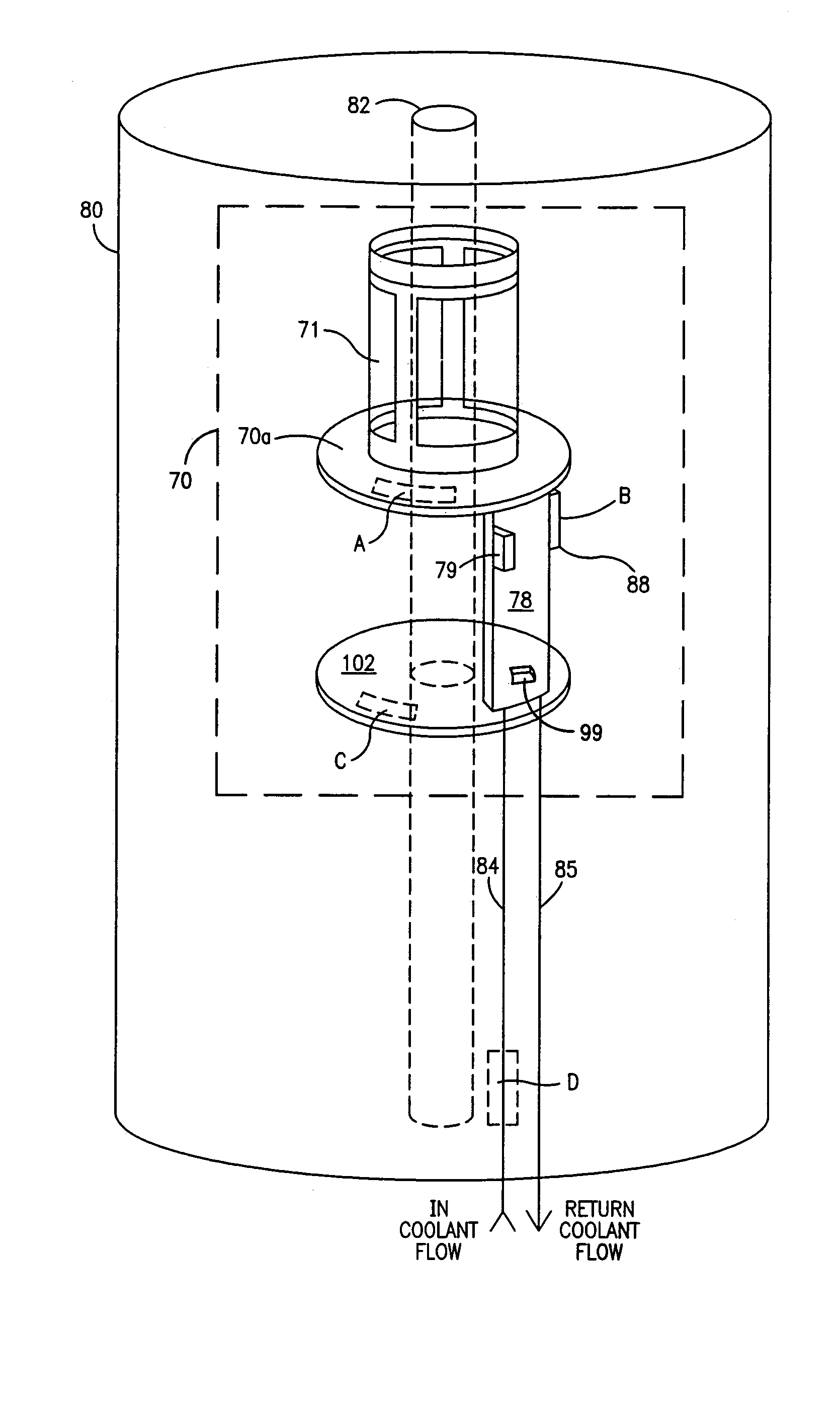
[0009]An NMR lineshape minimally affected by thermal fluctuation is one desiderata of the present work and this is achieved through improved thermal stability of the cold probe components. To this end, the heater supplying heat to the cold head heat exchanger is disposed in close proximity with that heat exchanger and preferably in conductive contact with the heat exchanger structure itself or with the RF coil support structure of the cold head. Robust and reliable cryo-pumping of residual gas in the probe cryostat and improved thermal regulation of the cold head are achieved by artful placement of the heater in respect of the heat exchanger. In one embodiment the heater is disposed proximate the heat exchanger with several consequences: (a) the coolant inflow conduit, prior (in flow direction) to the point of thermal communication with the heater, presents a more nearly constant temperature of the inlet capillary resulting in a substantially greater isothermal surface for cryo-stabilization of remanent gasses; (b) the magnetic homogeneity remains more stable under the applications of time varying RF loads to the probe; (c) the response time for compensating thermal excursions is reduced. In one embodiment a non-inductive heater supplies heat directly to the heat exchanger through conduction. In an alternative embodiment heat is transferred to the coolant inflow to the heat exchanger at substantially the inflow port of the heat exchanger without substantial extent of inflow conduit between heater and heat exchanger. In another embodiment, a heater of appropriate power capability is disposed directly on the cold head in direct (conductive) thermal communication with the RF coil flange or support structure. A temperature sensor appropriately disposed on the cold head provides a signal for control of the heater.

Problems solved by technology

A heat exchanger comprising a part of the cold head cools the cold head to somewhat below the operating temperature, while the application of RF power to the coil adds heat to the environment and increases the thermal load on the heat exchanger with a resulting temperature rise.
Salient of these is variation with temperature of magnetic susceptibility of materials employed in the environs of the cold head resulting in magnetic field disturbance in the neighborhood of the sample; temporal variation of temperature over lengthy data acquisition, and the stability of various parameters of the equipment.
The cryo-pumped vapors (principally hydrogen) are in some degree released with consequent deleterious effect as increased RF noise.

Method used


Image

  • Cryogenic NMR probe
  • Cryogenic NMR probe
  • Cryogenic NMR probe

Examples


Embodiment Construction

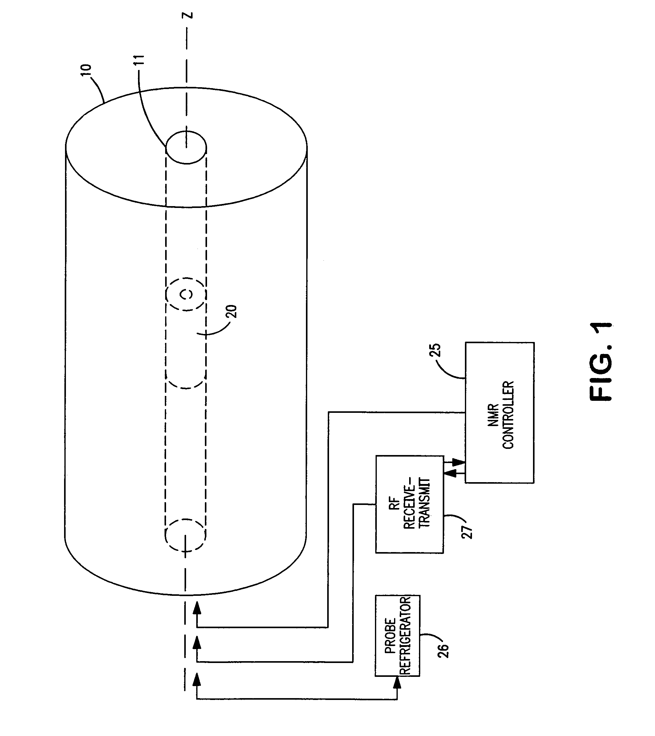
[0015]The context of the present work is conveniently described with the aid of FIG. 1. Please note that wherever convenient, the same numeric label is retained among the several embodiments and figures.

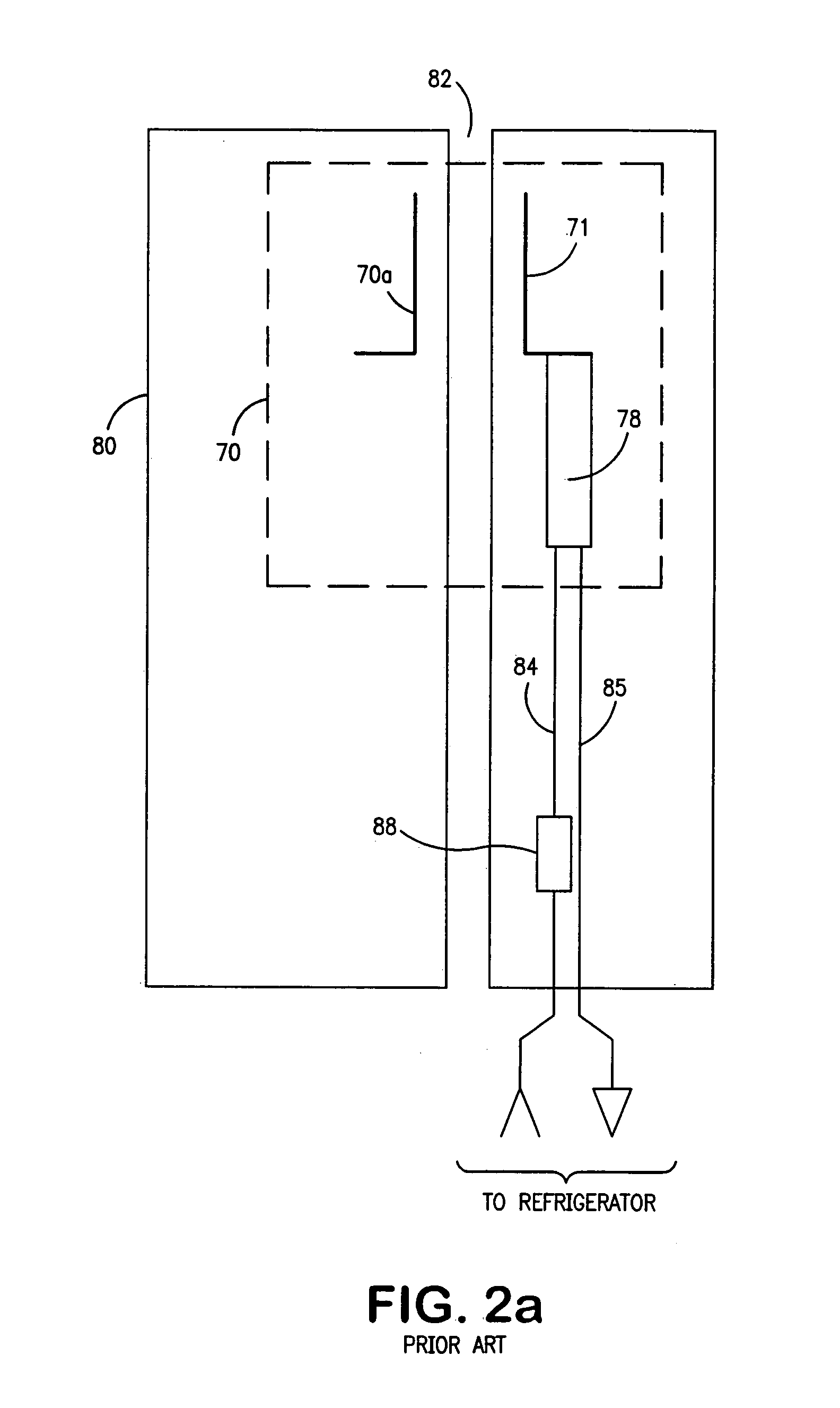
[0016]A superconducting magnet cryostat 10 includes a bore 11. A probe cryostat 20 has a similar outer annular geometry coaxial with bore 11 and a central coaxial bore of cryostat 20 defining a sample bore 82 shown in FIG. 2a. The sample (not shown) is typically studied at room temperature or some selected temperature. The sample is thermally isolated from the internal low temperature of the probe cryostat 20 and introduced along axis z. Magnet cryostat 10 and probe cryostat 20 are typically separate and independent structures although this is not a requirement. Refrigeration for probe cryostat 20 as well as RF and DC power and control signals are communicated to probe cryostat 20 through bore 11. Probe refrigerator unit 26 is of known design as is RF receive-transmit unit 27.

[0017]O...


PUM


Abstract

The thermal performance and vacuum properties of a cryogenic NMR probe are improved when thermal control is implemented by conductive heat transfer to a cold head cooled by a heat exchanger to below the selected operating temperature. The heat load is manipulated by locating a heater to produce a more nearly constant heat load in conjunction with pulsed RF power and in one embodiment transferring such heater power through a common thermal path. In another embodiment, the heater power is conductively transferred directly to the heat exchanger.

Description

RELATED APPLICATION DATA[0001]This application is related to the U.S. patent application entitled “Efficiently Cryo-pumped NMR Cryogenic Probe” by the inventors Thomas Barbara and Alexander M. J. Hudson, which application is filed concurrently with the present application and assigned to the assignee of the present application.BACKGROUND OF THE INVENTION[0002]The present work is in the field of NMR apparatus and relates particularly to an NMR probe operating at cryogenic temperatures.[0003]An NMR probe coil couples an RF transmitter / receiver to sample nuclei. Operation of the RF coil at cryogenic temperatures contributes a very high efficiency through enhanced Q of the resonant circuit and significant reduction of Johnson noise. These factors provide enhanced sensitivity for NMR spectra and have motivated considerable effort to realize an improved cryogenic NMR probe.[0004]A central component within the cryogenic probe is the “cold head” (that portion within the probe structure prov...

Claims


Application Information

Patent Timeline
Patent Type & Authority Patents(United States)
IPC IPC(8): G01V3/00
CPCG01R33/31G01R33/3403G01R33/34G01R33/34023
Inventor BARBARA, THOMAS M.HUDSON, ALEXANDER M. J.GIBSON, ATHOLL A. V.
Owner AGILENT TECH INC
Learn More