Method and apparatus for electronic cancellation of quadrature error

a quadrature error and electronic cancellation technology, applied in the field of mems gyroscopes, can solve the problems of high cost of high-volume mems gyroscopes, high signal-to-noise ratio, and inability to produce low-cost products cost-effectively, etc., to achieve the effect of reducing quadrature error, high signal-to-noise ratio, and more accurate measurement of the rate of rotation

Active Publication Date: 2007-11-06
INVENSENSE
View PDF10 Cites 66 Cited by
  • Summary
  • Abstract
  • Description
  • Claims
  • Application Information

AI Technical Summary

Benefits of technology

[0014]The quadrature error cancellation signal can be derived from a drive signal within the drive circuit that is used to vibrate the proof mass. The quadrature error cancellation circuit can further include an amplitude scaling circuit operable to scale the drive signal and generate the quadrature error cancellation signal based on the scaled drive signal. The quadrature error cancellation circuit can further include a memory operable to store one or more pre-determined digital codes that each represents a particular scale factor for scaling the drive signal. The amplitude scaling circuit can scale the drive signal based on a selected one of the one or more pre-determined digital codes to minimize quadrature error within the sensed change in charge.
[0015]Implementations may provide one or more of the following advantages. A MEMS gyroscope is provided that includes a quadrature error cancellation circuit that substantially cancels quadrature error prior to conversion of sensed capacitance (charge) change associated with a Coriolis signal being converted to a voltage or current. In one implementation, the quadrature error is substantially cancelled at the input of a sense mass position sensor circuit (which includes a C-I or C-V circuit). Accordingly, the invention avoids the need for large voltages to apply an electrostatic force to mechanical elements and avoids compromising position sensing electronics (e.g., the sense mass position sensor circuit) within a MEMS gyroscope. Thus, a MEMS gyroscope is provided that can retain a high signal-to-noise ratio and provide more accurate measurements of rate of rotation.

Problems solved by technology

Such voltages are generally greater than 10V and are relatively expensive in terms of silicon area (and thus product cost) to generate and control.
Such a technique generally requires expensive specialized instrumentation and test structures to trim the drive and sense mechanical elements while at the same time testing the gyroscope.
This technique, therefore, is not cost effective for the production of low cost, high volume MEMS gyroscopes.
However, the quadrature error signal can be so large that operation of the C-to-V or C-to-I circuit is severely impacted—that is, the dynamic range of the input of the C-to-V or C-to-I circuit must accommodate the large quadrature error as well as the small Coriolis signal.

Method used


Image

  • Method and apparatus for electronic cancellation of quadrature error
  • Method and apparatus for electronic cancellation of quadrature error
  • Method and apparatus for electronic cancellation of quadrature error

Examples


Embodiment Construction

[0023]The present invention relates generally to MEMS gyroscopes, and methods for compensating for quadrature error in MEMS gyroscopes. The following description is presented to enable one of ordinary skill in the art to make and use the invention and is provided in the context of a patent application and its requirements. Various modifications to the preferred implementations and the generic principles and feature described herein will be readily apparent to those skilled in the art. Thus, the present invention is not intended to be limited to the implementations shown but is to be accorded the widest scope consistent with the principles and features described herein.

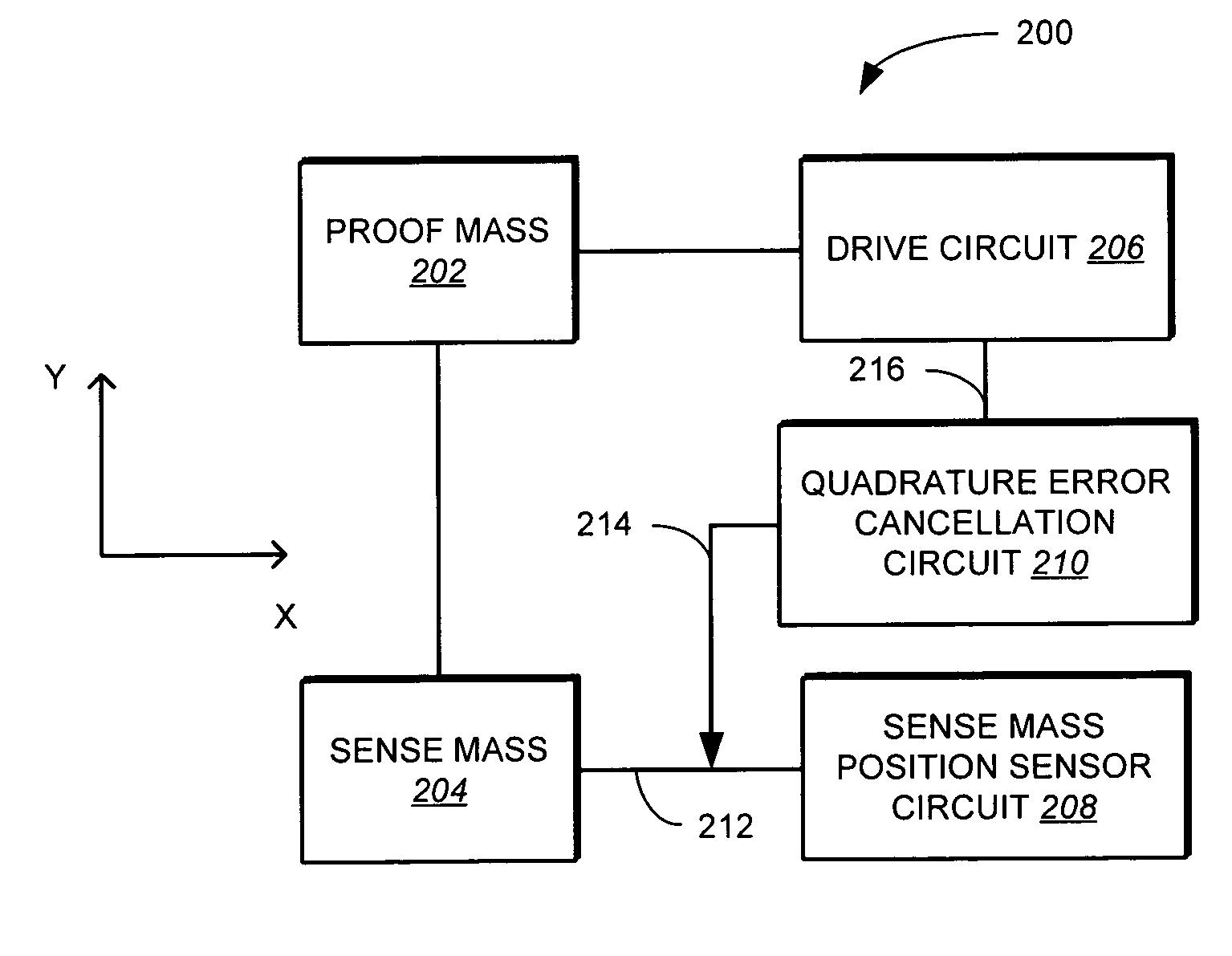
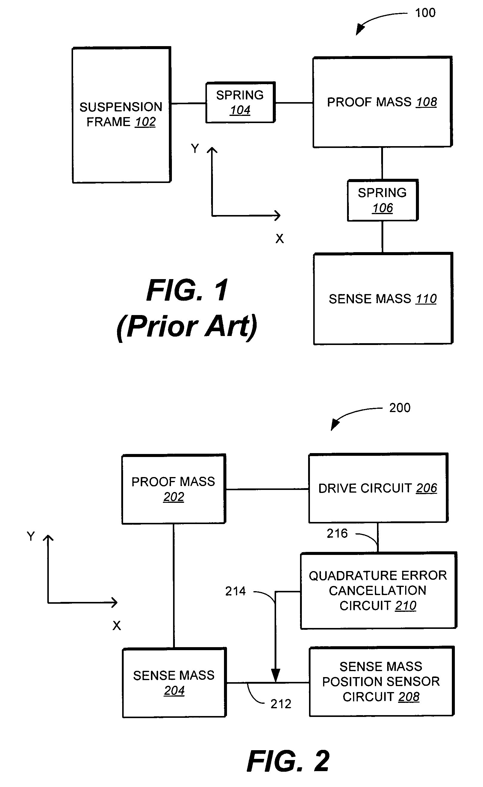
[0024]FIG. 2 shows a MEMS gyroscope 200 in accordance with the invention. MEMS gyroscope 200 can be a MEMS gyroscope as described in U.S. Pat. No. 6,892,575 —entitled “X-Y Dual-Mass Tuning Fork Gyroscope With Vertically Integrated Electronics and Wafer-Scale Hermetic Packaging”, assigned to the assignee of the present ...


PUM


Abstract

Methods and apparatus are provided for detecting a rate of rotation. In one implementation, the method includes vibrating a proof mass at a pre-determined frequency in a drive axis. In response to a rotation, sensing an amount of deflection of the proof mass in an axis orthogonal to the drive axis, in which the amount of deflection is sensed as a change in charge. The method further includes generating a quadrature error cancellation signal to substantially cancel quadrature error from the sensed change in charge.

Description

FIELD OF THE INVENTION[0001]The present invention relates generally to MEMS gyroscopes, and in particular methods for compensating for quadrature error in MEMS gyroscopes.BACKGROUND OF THE INVENTION[0002]Measuring rate of rotation is generally implemented through the use of gyroscopes. Gyroscopes can be fabricated using MEMS (microelectromechanical systems) techniques.[0003]FIG. 1 shows a conventional MEMS gyroscope 100 for measuring rate of rotation. MEMS gyroscope 100 includes a suspension frame 102, springs 104-106, a proof mass 108, and a sense mass 110. Proof mass 108 and sense mass 110 are suspended to suspension frame 102 by springs 104-106. In operation, proof mass 108 is vibrated (or driven), e.g., by electrostatic actuation, along the x-axis and (ideally) sense mass 110 does not move. In response to a rotation about the z-axis, proof mass 108 deflects out of the drive axis (i.e., the x-axis) and exhibits a vibration in an axis (i.e., the y-axis) that is orthogonal to the d...

Claims


Application Information

Patent Timeline
Patent Type & Authority Patents(United States)
IPC IPC(8): G01P21/00
CPCG01C19/5719G01C19/5726
Inventor SEEGER, JOSEPHRASTEGAR, ALITORMEY, MILTON T.
Owner INVENSENSE
Why Eureka
Try Eureka