Internal shock absorber bypass plunger

a technology of shock absorber and plunger, which is applied in the direction of drilling casings, wellbore/well accessories, drilling pipes, etc., can solve the problems of gas phase not being able to support liquid in slug form or droplet form, reducing the lifting efficiency, and reducing the impact force of the plunger, so as to reduce the impact force and reduce the impact time. , the effect of shortening the plunger fall tim

Active Publication Date: 2007-11-06
CHAMPIONX LLC
View PDF45 Cites 36 Cited by
  • Summary
  • Abstract
  • Description
  • Claims
  • Application Information

AI Technical Summary

Benefits of technology

[0023]The present apparatus provides a plunger lift system having a bypass feature that can allow for a shorter plunger fall time. Because the increased speed of travel typically results in a greater likelihood of impact, a greater impact force, and potential damage, the present apparatus incorporates a system for absorbing the resulting shock. In addition, the rate of the plunger's speed can be adjusted though the use of either fixed or variable orifice valves.
[0024]The present apparatus provides a plunger lift system with a more reliable shock absorber. With more reliability, wells could be constructed with or without bumper spring assemblies, which typically operate to slow a plunger's travel. In well applications which do not utilize bumper spring assemblies, fewer obstructions or restrictions are encountered by a plunger at the well bottom. In these cases, plunger travel can be more optimal and plunger damage can be reduced or minimized.
[0025]By utilizing an internal placement of the shock absorbing components, plunger structure has less effect on the physical restrictions of a well bottom and any equipment housed therein. The present apparatus can be used if a reduction of well top damage (as in the case of high velocity plunger rise) and a reduction of well bottom damage (as in the case of high velocity plunger fall), is desired. In addition, the components of the present apparatus are easy to manufacture and easy to assemble.

Problems solved by technology

As flow rate and pressures decline in a well, lifting efficiency can decline.
First, as liquid comes in contact with the wall of the production string of tubing, friction occurs.
Secondly, as the flow velocity continues to slow, the gas phase may no longer support liquid in either slug form or droplet form.
Because of the small tubing diameters, a relatively small amount of liquid may cause a well to load-up, or a relatively small amount of paraffin may plug the tubing.
When a plunger falls slowly to the bottom of a well, well efficiency is not maximized.
Fluid build up can hamper the plunger's descent during the return trip to the bumper spring located at the well bottom.
Thus, wells with a high fluid level tend to lower well production by delaying the cycle time of the plunger system, specifically delaying the plunger return trip to the well bottom.
In other words, plunger fall time can affect well production.
A higher velocity could lead to greater impact force and can result in damage to the plunger, and / or the spring standing valve / bottom hole bumper assembly.
Bumper springs could collapse over time due to repeated stress caused by impact force.
Also, plunger damage can occur resulting in more frequent plunger replacement.
A high velocity rise could cause damage to the well top apparatus and to the plunger itself.
Damage to well apparatus and plunger lift equipment typically increases well maintenance cost.

Method used


Image

  • Internal shock absorber bypass plunger
  • Internal shock absorber bypass plunger
  • Internal shock absorber bypass plunger

Examples


Embodiment Construction

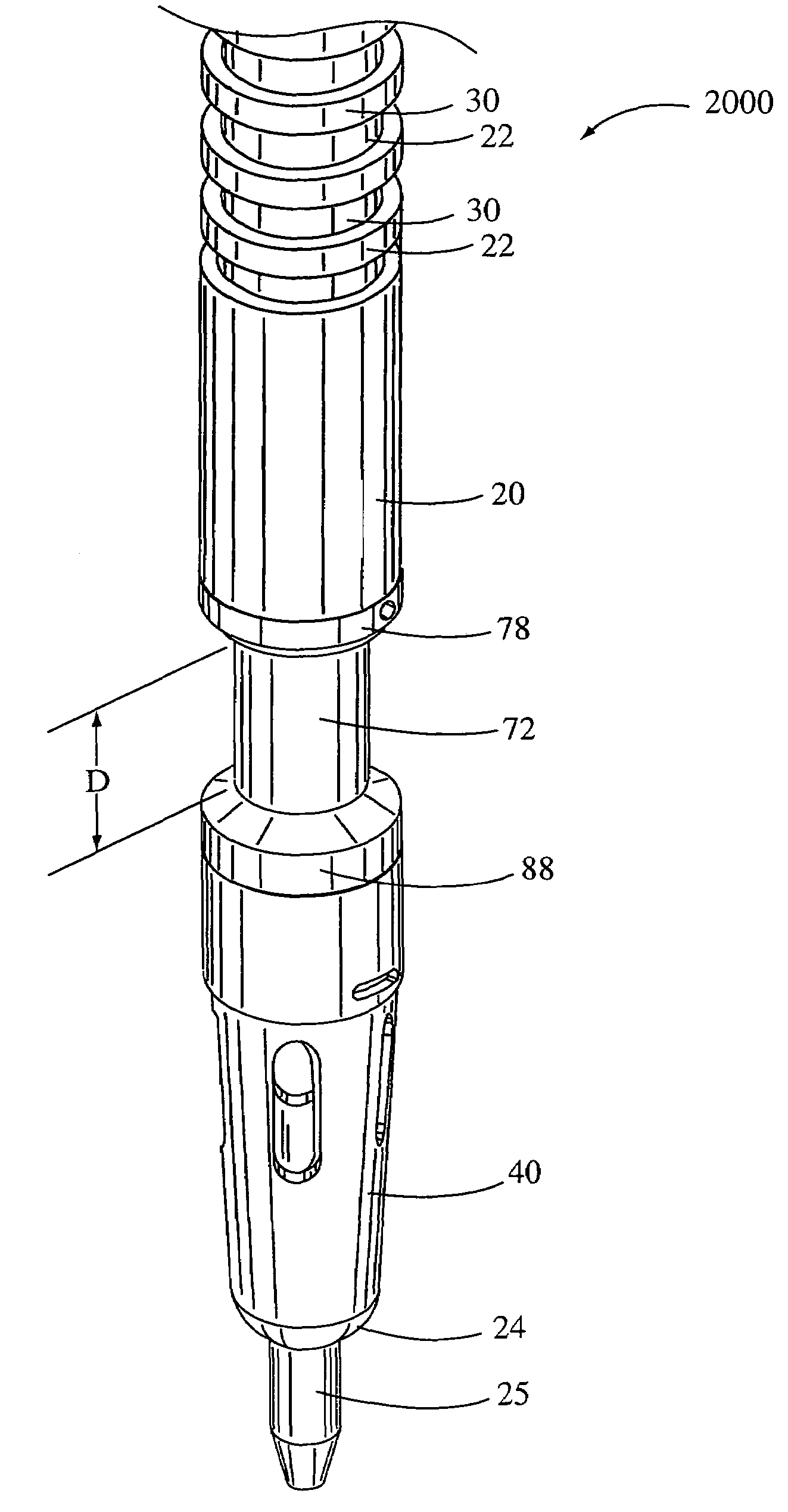
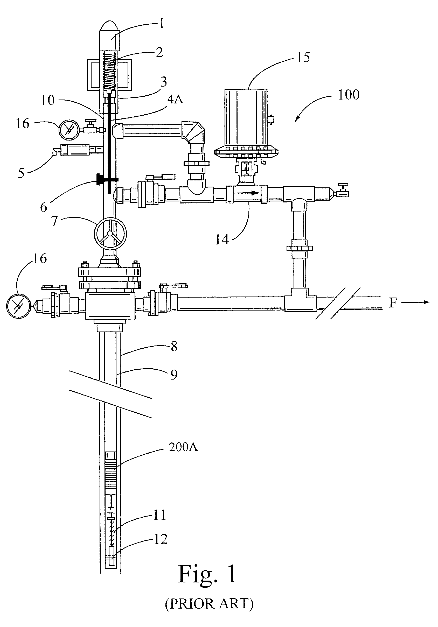
[0054]The drawings depict an internal shock absorber bypass plunger apparatus that can improve productivity levels in high liquid wells when plunger falling velocity produces a large impact force at the well bottom. The present apparatus can be used in well applications with or without a bumper spring. As stated above, high velocity lift will occur in low liquid wells, as well as instances when an operator will cycle the plunger prior to liquid loading. The present invention can also protect the plunger and the apparatus at the well top in the case of a high velocity lift.

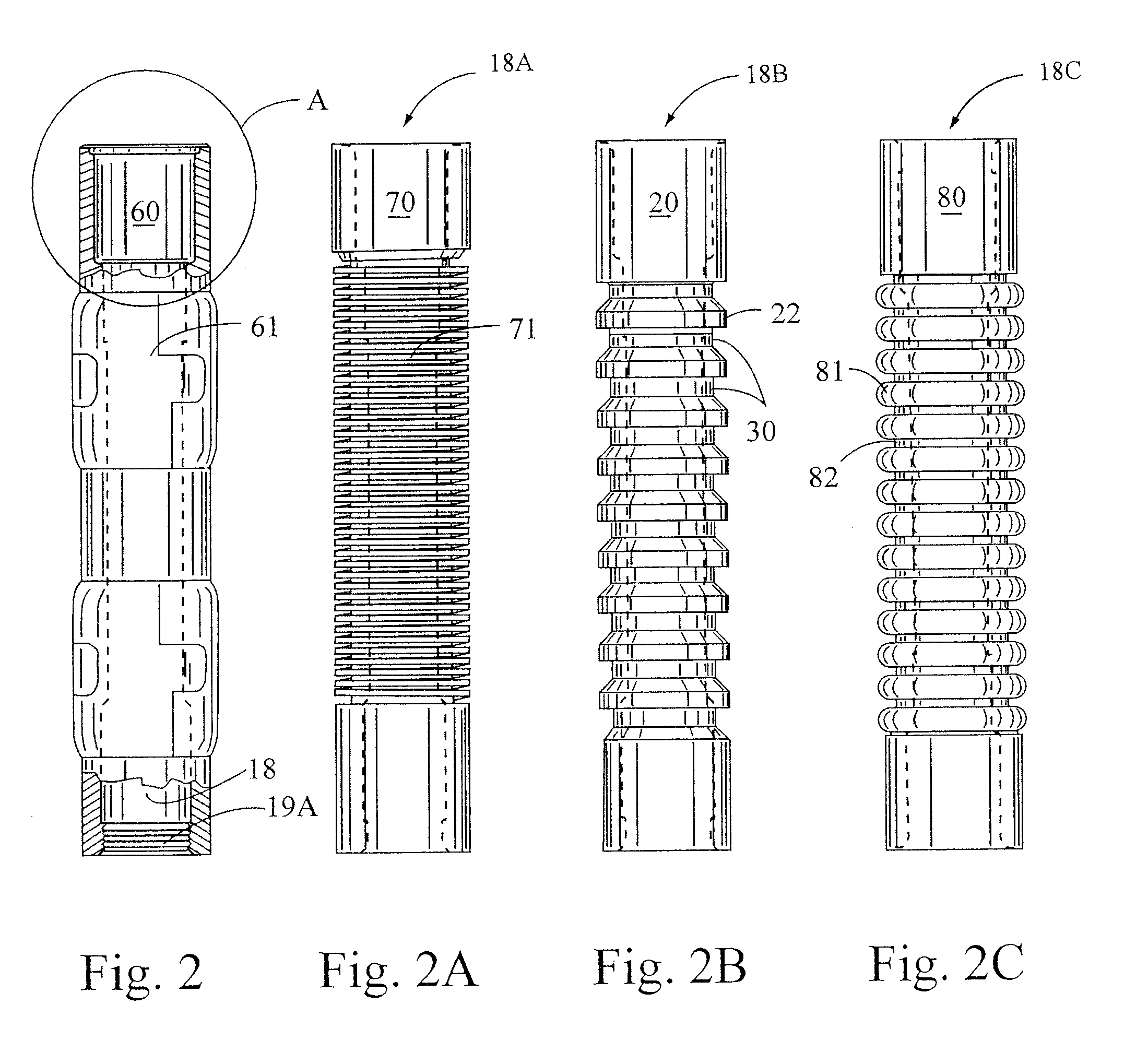
[0055]Generally the disclosed apparatus comprises a mandrel (cylindrical body) section, a captive actuator assembly housing a shock absorbing element (shock absorbing assembly), a bypass valve assembly section having an actuator rod and functioning to open or close an inlet to an internal conduit within the plunger, thus allowing fluid to pass through the plunger when falling (open position) and not allowing fluid ...


PUM


Abstract

A bypass plunger having one or more internal shock absorbing elements and a variety of bypass orifice options is disclosed.

Description

FIELD OF THE INVENTION[0001]The present invention relates to a plunger lift apparatus for the lifting of formation liquids in a hydrocarbon well. More specifically the plunger comprises an upper bypass mandrel, an internal shock absorber plunger section and a lower bypass valve. The shock absorbing bypass plunger operates to absorb shock during plunger falls to a well bottom, and high velocity rises to the well top, while providing for a bypass function during plunger travel.BACKGROUND OF THE INVENTION[0002]A plunger lift is an apparatus that is used to increase the productivity of oil and gas wells. In the early stages of a well's life, liquid loading is usually not a problem. When rates are high, the well liquids are carried out of the well tubing by the high velocity gas. As a well declines, a critical velocity is reached below which the heavier liquids do not make it to the surface and start to fall back to the bottom exerting back pressure on the formation, thus loading up the ...

Claims


Application Information

Patent Timeline
Patent Type & Authority Patents(United States)
IPC IPC(8): E21B43/00
CPCE21B17/1071E21B17/07
Inventor VICTOR, BRUCE M.
Owner CHAMPIONX LLC
Why Eureka
Try Eureka