
Impeller hub for torque converter

a technology of impeller hub and torque converter, which is applied in the direction of fluid gearing, rotary clutch, liquid fuel engine components, etc., can solve the problems of eventual failure of the torque converter, and achieve the effect of improving the service life of the impeller hub and the pump bearing

Inactive Publication Date: 2007-11-06
SONNAX INDS
View PDF2 Cites 19 Cited by
  • Summary
  • Abstract
  • Description
  • Claims
  • Application Information

AI Technical Summary

Benefits of technology

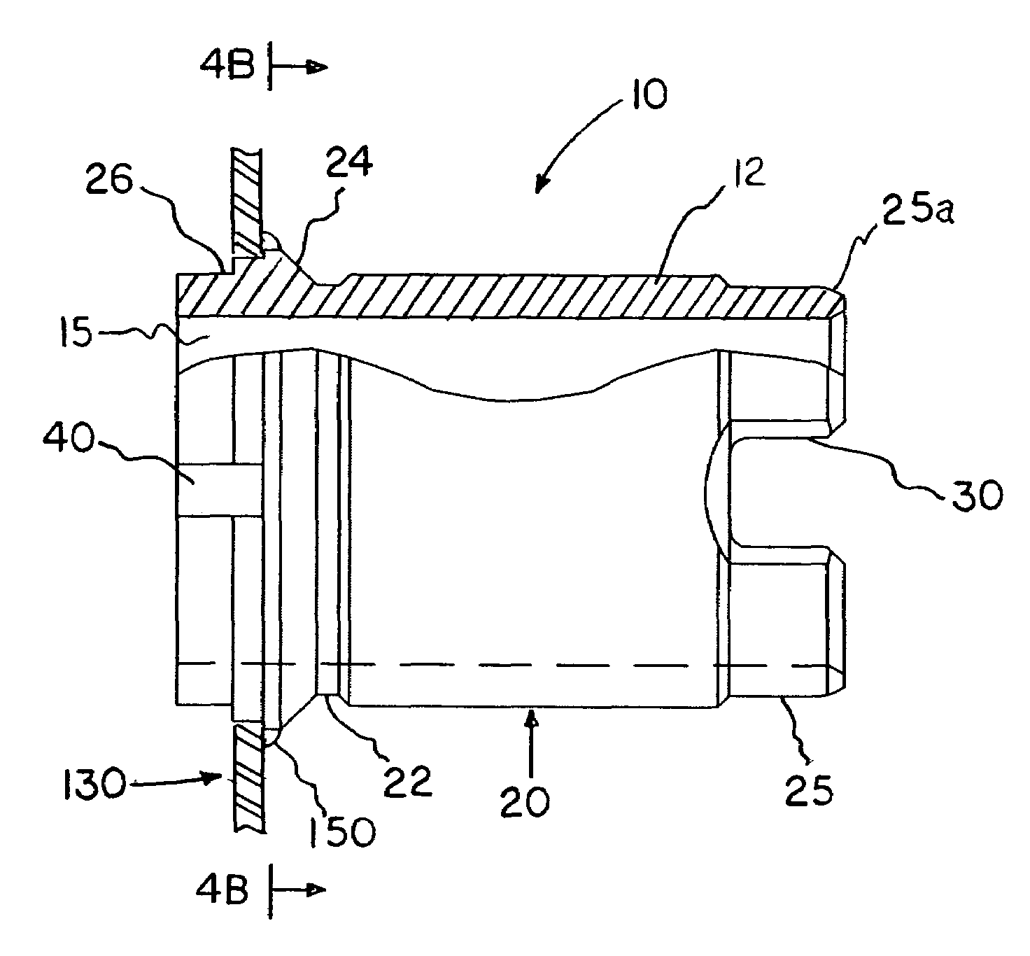
[0005]Accordingly, the present invention is a replacement impeller hub for use in an impeller assembly within the torque converter of an automatic transmission. Critical to the present invention, the geometric roundness characteristic of the impeller hub is controlled to 0.0003 inch during the present manufacturing process in accordance with American National Standards Institute (hereinafter “ANSI”) Y 14.5M definitions to provide a close tolerance fit and to maximize surface-to-surface contact with its mating bearing sleeve located within the hydraulic pump. Conformance to this 0.0003 roundness characteristic has been demonstrated to substantially improve the service longevity of the impeller hub and pump bearing.
[0006]The present impeller hub is also finish ground in accordance with ANSI Y 14.36M definitions to provide a fine surface texture reducing surface friction and providing an optimal sealing surface for engagement with a radial lip seal, which is disposed about the impeller hub surface sealing it to prevent contaminants from entering the hydraulic pump. The present impeller hub is also induction hardened in accordance with industry specification MIL-H-6875 to improve abrasion resistance and to reduce mechanical wear.

Problems solved by technology

Because the impeller hub projects through the transmission case and is exposed to exterior dirt and contaminants, premature wear of the mating bearing and seal can occur resulting in eventual failure of the torque converter.

Method used


Image

  • Impeller hub for torque converter
  • Impeller hub for torque converter
  • Impeller hub for torque converter

Examples


Embodiment Construction

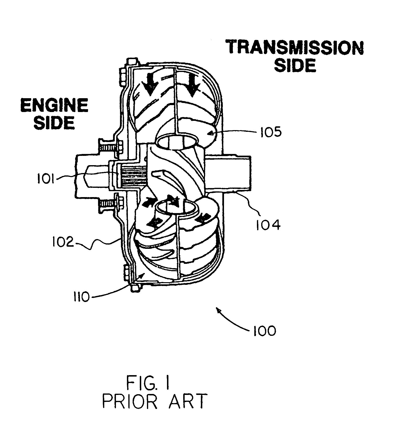
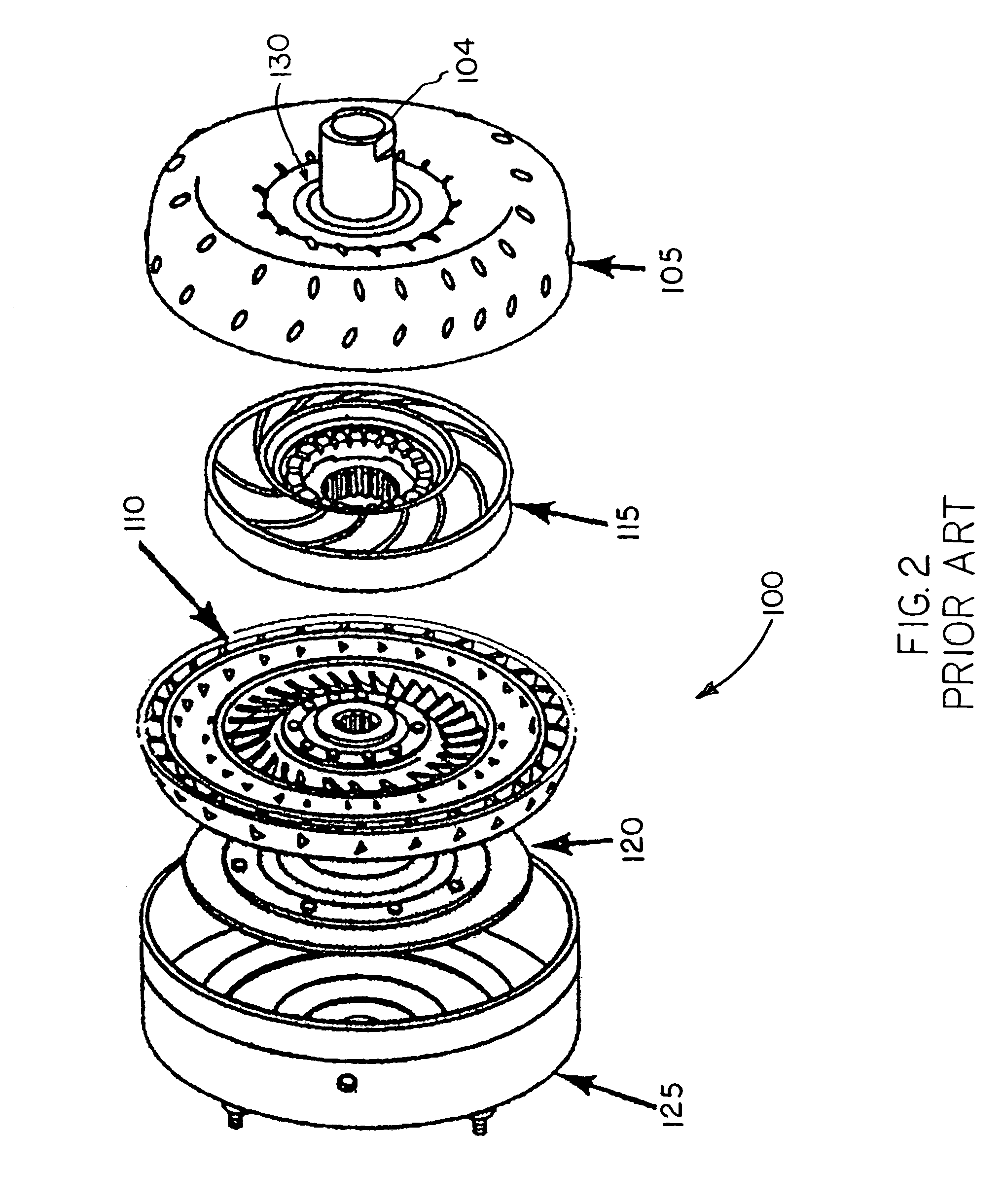
[0026]Prior to describing the present invention in detail, it may be beneficial to briefly review the structure and function of the torque converter of an automatic transmission. The torque converter is the primary component for transmittal of power between the engine and the automatic transmission or transaxle in an automotive vehicle. As shown in FIGS. 1 and 2, the torque converter assembly, indicated generally at 100, is bolted to the engine flywheel 102 (also known as the flexplate) so that it will rotate at engine speed. The torque converter assembly 100 provides for a smooth conversion of torque from the engine to the mechanical components of the transmission. The torque converter assembly 100 also functions to multiply torque from the engine enabling the vehicle to achieve additional performance when necessary.

[0027]The torque converter assembly 100 is made up of the following main sub-assemblies: (1) an impeller or converter pump assembly, indicated generally at 105, which i...


PUM

PropertyMeasurementUnit
Lengthaaaaaaaaaa
Angleaaaaaaaaaa
Molar densityaaaaaaaaaa

Abstract

A direct replacement impeller hub for the torque converter of an automatic transmission and a method of repairing an impeller assembly utilizing the replacement impeller hub to provide increased service longevity. In the present impeller hub the geometric roundness characteristic of the impeller hub is controlled to an exacting tolerance during the manufacturing process in accordance with American National Standards Institute (ANSI) definitions to provide a close tolerance fit within a mating bearing sleeve. The present impeller hub is also finish ground in accordance with ANSI definitions to reduce surface friction and to provide an optimal sealing surface for engagement with a radial seal, which is disposed about the impeller hub sealing it to prevent contaminants from entering the hydraulic pump of the transmission. The present impeller hub also includes additional structural features such as fillet radii machined on selected features to facilitate assembly of the torque converter.

Description

CROSS-REFERENCE TO RELATED APPLICATIONS[0001]This application claims the benefit under 35 U.S.C. 119(e) of U.S. Provisional Patent Application No. 60 / 510,655 filed Oct. 14, 2003 entitled Impeller Hub for Torque Converter.BACKGROUND OF INVENTION[0002]The present invention relates to torque converters for automatic transmissions in land vehicles and, more particularly, to an impeller hub, which comprises a part of the impeller assembly in such a torque converter.[0003]The torque converter of an automatic transmission replaces the clutch used in manual transmissions. It is the primary component for transmittal of power between the engine and the transmission in an automotive vehicle. The basic principle of torque converter operation can be observed by placing the blades of two electric fans opposite each other and turning on one of the fans. If one of the fans is turned on, the force of the air column produced will act upon the motionless blades of the other fan, which will begin turni...

Claims


Application Information

Patent Timeline
IPC IPC(8): F16D33/18
CPCF16H41/24
Inventor MORIN, MICHAEL G.
Owner SONNAX INDS
Learn More