Artificial disc replacement (ADR) using elastic tether member

a technology of elastic tether and artificial disc, which is applied in the field of prosthetic implants, can solve the problems of increasing the risk of separation of the artificial disc from the vertebrae above and below, increasing the changes of the future, and increasing the risk of dislocation of the artificial disc, so as to avoid dislocation, and reduce the risk of dislocation

Inactive Publication Date: 2007-11-06
ANOVA
View PDF37 Cites 79 Cited by
  • Summary
  • Abstract
  • Description
  • Claims
  • Application Information

AI Technical Summary

Benefits of technology

[0007]This invention is broadly directed to improved artificial disc (ADR) and joint replacement components, particularly those associated with the knee and hip. Most embodiments use compressible, resilient materials to approximate joint kinematics, often with elastic or spring components to tether articulating components to avoid dislocation, excessive compression, flexion or other out-of-range movements. The preferred embodiments include a robust design, requiring only two or a few articulating components. The designs allow for normal flexion, extension, lateral bending, rotation, and translocation, depending upon the application.
[0008]Most ADR embodiments do not require precise alignment. The ADR can be self-centering in versions that articulate with the endplates of the vertebrae. Alternative vertebral endplate resurfacing designs are also disclosed. Typical ADR embodiments combine a compressible component and a C-shaped or other containment component, to accommodate natural axial forces, relaxation, and bending movements. Further embodiments use the ADR EPs to force or wedge apart articulating components made of metal, or other material with good wear characteristics, as loads are applied.
[0009]In all embodiments, the articulating compone...

Problems solved by technology

Consequently, the discs adjacent to the fused level are subjected to increased stress, which increases the changes of future surgery to treat the degeneration of t...

Method used


Image

  • Artificial disc replacement (ADR) using elastic tether member
  • Artificial disc replacement (ADR) using elastic tether member
  • Artificial disc replacement (ADR) using elastic tether member

Examples


Embodiment Construction

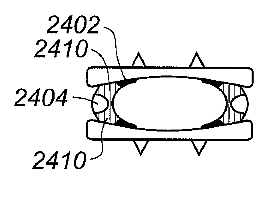
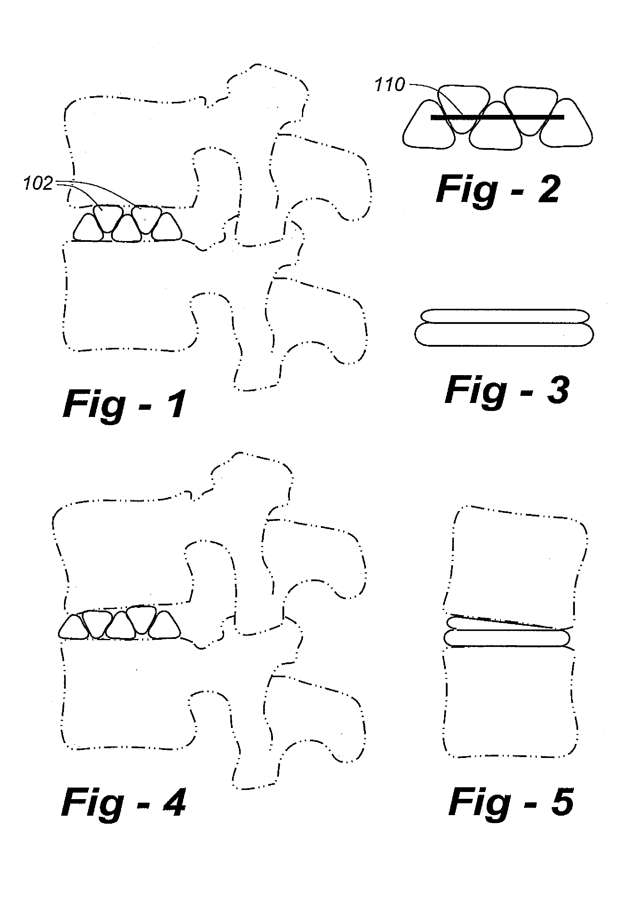
[0137]FIG. 1 is a view of the lateral aspect of the spine and an ADR according to the invention, including a plurality of articulating components 102. FIG. 2 is a sagittal cross section of the ADR, illustrating how the articulating components are connected by one or more springs or elastic bands 110. Using this configuration, the articulating components are free to position themselves to “custom fit” the endplates of the vertebrae.

[0138]FIG. 3 is a view of the anterior aspect of the ADR, and FIG. 4 is a view of the lateral aspect of the ADR in conjunction with a flexed spine. The anterior components slide against one another to decreases the height of the anterior aspect of the ADR during spinal flexion. The elastic tether returns the articulating components to their resting position as the spine is returned to its neutral position. The articulating components and the elastic tether also cooperate to dampen axial loads to the spine.

[0139]FIG. 5 is a view of the anterior aspect of sp...


PUM

PropertyMeasurementUnit
Elasticityaaaaaaaaaa

Abstract

Artificial disc (ADR) and joint replacement components, particularly those associated with the knee and hip, use compressible, resilient materials to approximate natural kinematics, often in conjunction with elastic or spring components to tether articulating components to avoid dislocation, excessive compression, flexion or other out-of-range movements. The preferred embodiments require only two or a few articulating components. The designs allow for normal flexion, extension, lateral bending, rotation, and translocation, depending upon the application.

Description

REFERENCE TO RELATED APPLICATIONS[0001]This application claims priority from U.S. Provisional Patent Application Ser. Nos. 60 / 416,749, filed Oct. 7, 2002; 60 / 417,346, filed Oct. 9, 2002; 60 / 442,971, filed Jan. 27, 2003; 60 / 443,815, filed Jan. 30, 2003; 60 / 445,489, filed Feb. 6, 2003; 60 / 445,958, filed Feb. 7, 2003. This application is also a continuation-in-part of U.S. patent application Ser. Nos. 10 / 434,931, filed May 9, 2003; 10 / 434,917, filed May 9, 2003; and 10 / 435,332, filed May 9, 2003 now U.S. Pat. No. 6,875,235 which claims priority from 60 / 379,462, filed May 10, 2002. The content of each application is incorporated herein by reference.FIELD OF THE INVENTION[0002]This invention relates generally to prosthetic implants and, in particular, to artificial intervertebral disc and joint replacement components with improved wear and kinematics.BACKGROUND OF THE INVENTION[0003]Improvements in prosthetic intervertebral disc and joint replacement components, and related surgical proc...

Claims


Application Information

Patent Timeline
IPC IPC(8): A61F2/44A61B17/86A61F2/00A61F2/30A61F2/32A61F2/34A61F2/36A61F2/38
CPCA61F2/34A61F2/38A61F2/441A61F2/4425A61B17/86A61F2310/0058A61F2/32A61F2002/30069A61F2002/30075A61F2002/30133A61F2002/30135A61F2002/302A61F2002/30245A61F2002/30311A61F2002/30327A61F2002/30364A61F2002/30372A61F2002/30405A61F2002/30433A61F2002/30517A61F2002/30563A61F2002/30566A61F2002/30568A61F2002/30578A61F2002/30616A61F2002/30649A61F2002/30673A61F2002/30878A61F2002/30934A61F2002/3401A61F2002/3429A61F2002/3448A61F2002/3493A61F2002/3611A61F2002/4415A61F2002/443A61F2002/448A61F2210/0061A61F2220/0025A61F2220/0033A61F2220/0041A61F2230/0004A61F2230/0015A61F2230/0065A61F2230/0071A61F2250/0039A61F2310/00017A61F2310/00023A61F2310/00029A61F2310/00203A61F2/30742A61F2002/30136
Inventor FERREE, BRET A.
Owner ANOVA
Why Eureka
Try Eureka