Motor stator teeth with insulators

a technology of stator teeth and motors, which is applied in the direction of windings, dynamo-electric components, synchronous machines, etc., can solve the problems of limiting the improvement of the slot-fill factor of the coil, the failure of the conductor, etc., and achieves the effect of reducing the thickness of the coil, preventing the separation of the conductor, and smooth coil construction

Active Publication Date: 2007-11-06
NIDEC CORP
View PDF12 Cites 26 Cited by
  • Summary
  • Abstract
  • Description
  • Claims
  • Application Information

AI Technical Summary

Benefits of technology

[0007]The present invention makes it possible to build coils smoothly onto an electric motor stator. The present invention also makes it possible to reduce the thickness of coils on stator insulator surfaces, and to prevent the conductors from separating from the insulators.
[0008]In one example of the present invention, an electric motor stator comprises multiple teeth radially arrayed and centered on a specified center axis, insulators respectively covering said multiple teeth, and multiple coils constructed by winding multiple layers of conductors on said multiple teeth starting from said insulators. In an top end section which covers an top end and forms one end in a direction along the respective center axes of said multiple teeth, said insulator is provided with multiple upper guide grooves which are arrayed in parallel to one another at a pitch approximately equal to the diameter of said conductor, and which restrict the winding position of said conductor.
[0011]The present invention permits the smooth construction of coils. In particular, it enables the smooth construction of coils by preventing conductor mis-winding at the top end of the multiple teeth.

Problems solved by technology

For example, in stator implementations in which the insulators are formed with tooth-flank guide grooves, it can happen that the conductors fail to be guided by the guide grooves, which is prohibitive not only of attaining evenly-rowed wrapping but also of smooth conductor windings, and limits improvement in the slot-fill factor of the coils.

Method used


Image

  • Motor stator teeth with insulators
  • Motor stator teeth with insulators
  • Motor stator teeth with insulators

Examples


first embodiment

Overall Motor Structure

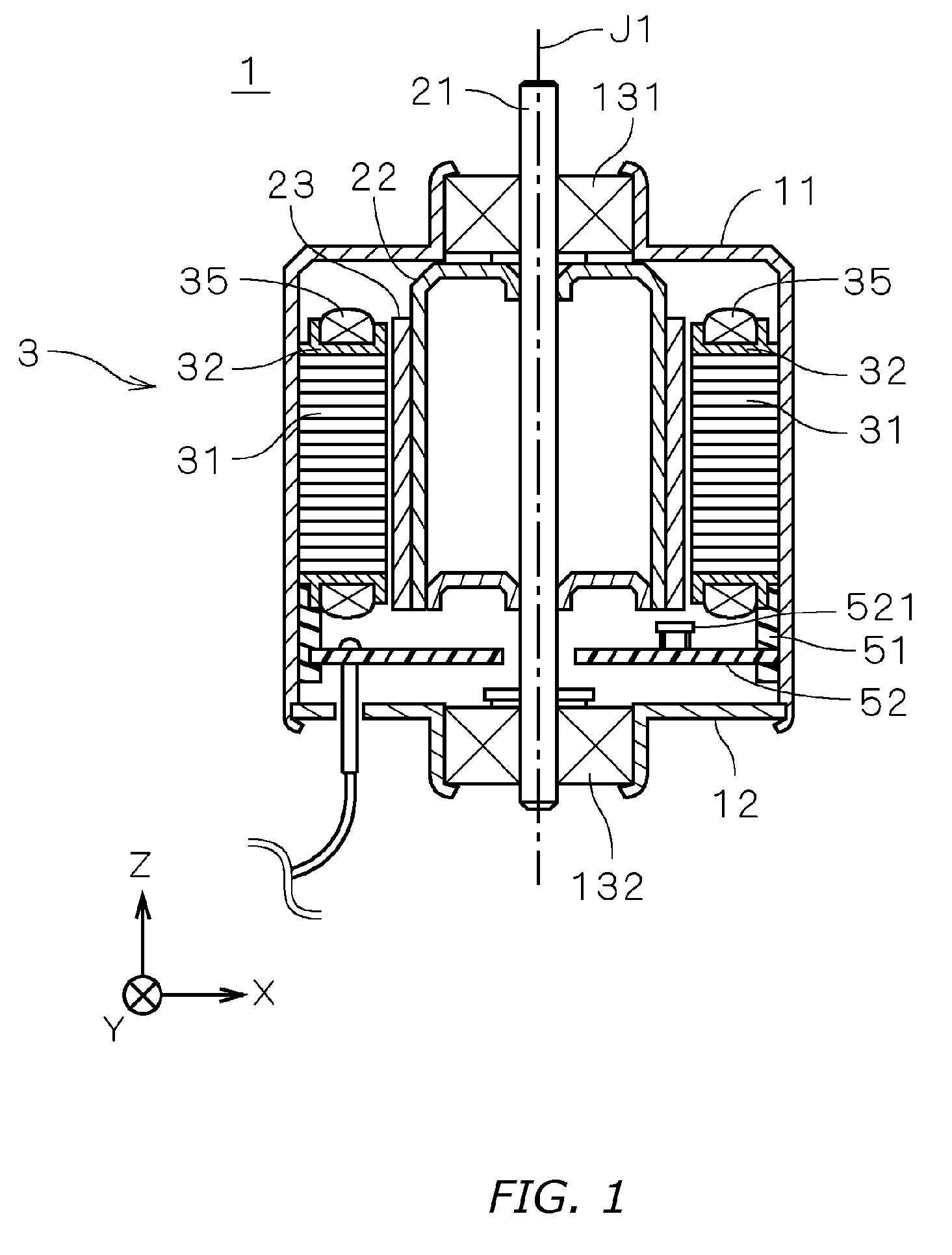
[0031]FIG. 1 is a vertical section showing an electric inner rotor-type motor 1 according to a first embodiment of the present invention. In the diagram, the motor 1 is covered by a cylindrical housing 11 with a small opening on the (+Z) side and a large opening on the (−Z) side in the diagram, and by a cover plate 12, which covers all but the center section of the opening on the (−Z) side. Ball bearings 131, 132 are fit respectively onto the housing 11 (+Z) side opening and onto the cover plate 12 opening, and a shaft 21 is rotatably supported by the ball bearings 131, 132. In the explanation that follows, the (+Z) and (−Z) sides along the motor 1 center axis J1 are respectively described as the upper and lower sides for the sake of convenience, but there is no requirement that the center axis J1 necessarily conform to the direction of gravity.

[0032]A cylindrical rotor yoke 22 is attached to the shaft 21 inside the housing 11, and a multipole magnetized field...

second embodiment

[0076]FIGS. 14 and 15 are respectively a plan view and a bottom view showing the region of an insulator 32 in a motor stator according to a second embodiment of the present invention. In a motor according to the second embodiment, a plurality of insulators 32a is disposed in place of the plurality of insulators 32 shown in FIG. 1. Other structures are the same as in FIG. 1, and the same reference numerals are used in the explanation below.

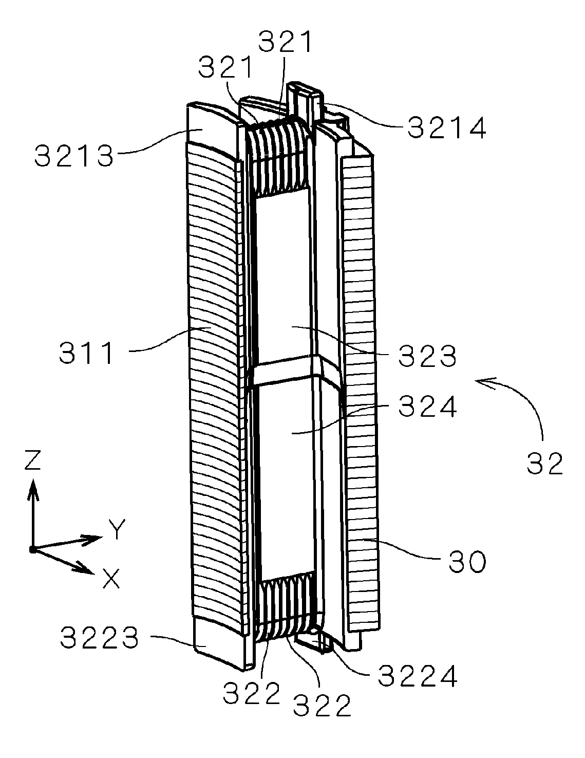
[0077]In a motor according to a second embodiment, as with the motor 1 according to the first embodiment, insulators 32a are provided with a first partition 323 and a second partition 324 respectively attached on the (+Z) side and the (−Z) side of the teeth 31 (cf. FIG. 6). A plurality of first guide grooves 321 is formed at the upper end portion of the first partition 323, and a plurality of second guide grooves 322 is formed at the lower end portion of the second partition 324.

[0078]As shown in FIGS. 14 and 15, the difference in radial distance (...

third embodiment

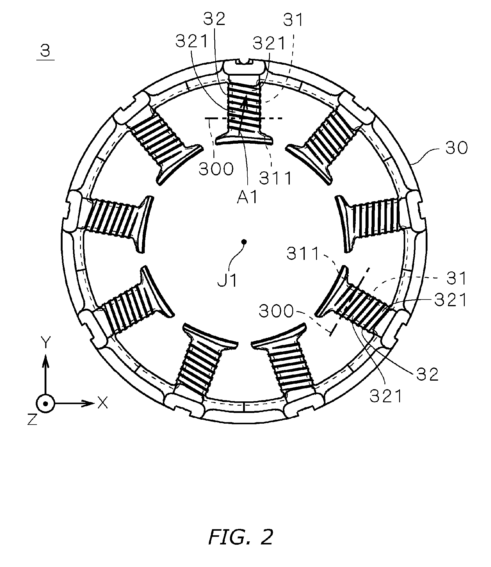
[0083]FIGS. 16 and 17 are partially sectional views showing one insulator's first partition 323a and second partition 324a in a motor stator according to a third embodiment of the present invention. The ““shaded area indicated by parallel slanted lines, as in FIGS. 8 and 9, is a section through an imaginary plane 300 (cf. FIG. 2) which is parallel to the center axis J1 and perpendicular to the teeth 31. Each of the insulators in the motor according to the third embodiment is the same as those in FIG. 1 with the exception that the sectional shape of the end section differs slightly in the direction parallel to the center axis J1. The same reference numerals are used in the explanation below.

[0084]As shown in FIG. 16, in the first partition 323a, a first crown section 3232, which is the most (+Z)-ward, distal edge of the end portion on the partition side where the first guide grooves 321 are formed, is positioned closer to the start point side than the end point side of the conductor ...


PUM


Abstract

A motor stator in one implementation includes a plurality of teeth disposed in a radial form centered about a predetermined center axis, insulators covering the plurality of teeth, and a plurality of coils provided on each of said plurality of teeth by winding conductors onto the insulators through to multiple layers. At one axial end of the plurality of areas where the insulators cover each of the plurality of teeth, the radius of curvature of the conductor windings on the ending side is larger than the radius of curvature on the starting side. The insulators in a motor stator in another implementation are provided with a first partition and a second partition that, relative to the axial center of the plurality of teeth, respectively cover one side and the other side each tooth.

Description

BACKGROUND OF THE INVENTION[0001]1. Technical Field[0002]The present invention relates to electrically powered motors, and in particular, to stators.[0003]2. Description of the Related Art[0004]Electrically powered motors to date have been furnished with a stator, and with magnetic-field producing magnets, which are the drive part that rotates a motor's rotor section relative to its stator section. Stators include an annular core, insulators as nonconducting components that cover teeth sections of the core, and coils formed by wrapping conductors onto the insulators. In midsized motors such as are used for “electric power steering systems” (as termed in, for example, U.S. Pat. App. Pub. No. 2002 / 0175574, but also referred to as “steer-by-wire systems”), conductors of relatively large diameter are wrapped around insulators and employed as the coils.[0005]In such motors, owing to the fact that motor efficiency increases with conductor diameter, technology for improving the slot-fill f...

Claims


Application Information

Patent Timeline
Patent Type & Authority Patents(United States)
IPC IPC(8): H02K3/18H02K15/095H02K3/46
CPCH02K3/522H02K3/325
Inventor OTSUJI, MOTOFUMI
Owner NIDEC CORP
Why Eureka
Try Eureka