

Tuneable grating assisted directional optical coupler
a directional optical coupler and assisted grating technology, applied in the direction of optics, optical waveguide light guides, instruments, etc., can solve the problems of affecting the long-term affecting the reliability of the coupler, and the high cost of the circulator, so as to achieve good thermo-optical properties
- Summary
- Abstract
- Description
- Claims
- Application Information
AI Technical Summary
Benefits of technology
Problems solved by technology
Method used
Image

Examples
example 1
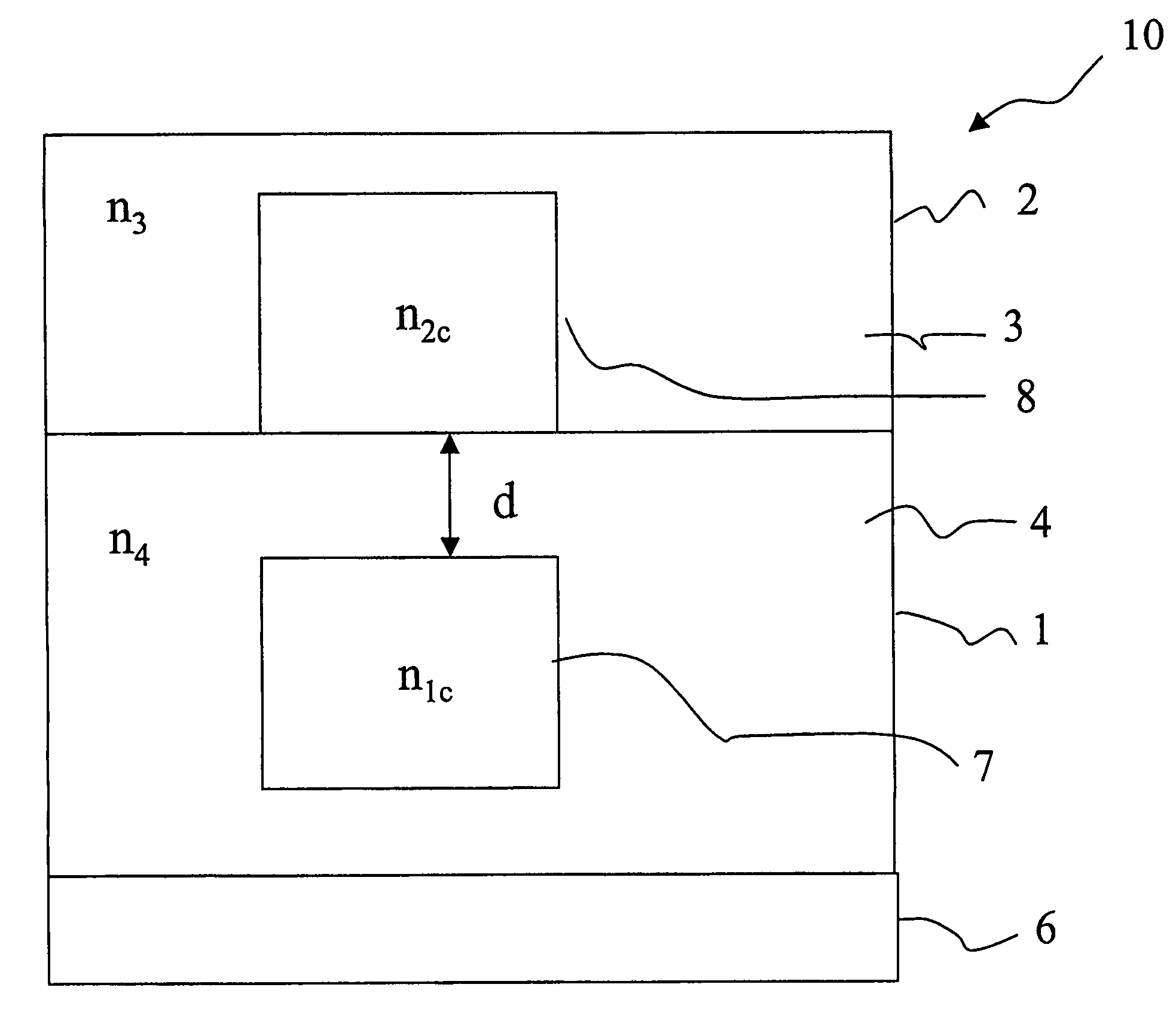
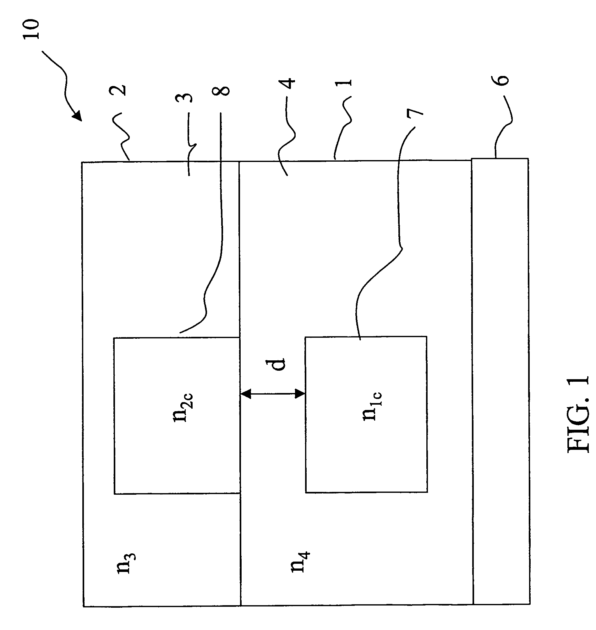
[0079]Referring again to FIG. 1, a contra-directional coupler 10 including two vertically stacked waveguides 1,2 on a substrate 6 is shown. The input waveguide in whose core also the grating is formed is the lower waveguide 1. The filtered wavelength is transferred to the upper waveguide 2. The core of the input waveguide 7 is square, its dimensions are 1.1×1.1 μm2 and it is realised in SiOx1Ny1 having a refractive index n1c of 1.7, while the core 8 of the output waveguide 2 is also square (1.1×1.1 μm2 as above) and it is realised in SiOx2Ny2 having a refractive index n2c of 1.567. The distance d between the two cores is 1.5 μm. The lower cladding material 4 is undoped silica, with a refractive index n4 of 1.446. The lower waveguide 1 and upper core 8 are fabricated following standard techniques. The last fabrication process is a deposition over the upper core 8 of the upper cladding 3, in particular by spin-coating, which is realized in DeSolite™ 3471-1-129 produced by DSM. This po...
example 2
[0080]FIG. 4 shows an alternative embodiment of a contra-directional coupler 10. The lower input waveguide 1 is realized as in example 1, while the upper waveguide 2 is an inverse ridge waveguide having the upper cladding 3 in a tuneable material, particularly in made of Sylgard™. In this example, the refractive index n3(T) of the upper cladding 3 goes from n3=1.4 to n3=1.37 for a temperature variation of 103° C. (the thermo-optic coefficient is equal to −2.9×10⁻⁴ / ° C.). Upper core 8, lower core 7 and lower cladding 4 are made of silicon-compounds materials. This structure may be advantageous because an accurate control of the thickness of the core—and thus of the coupler birefringence—can be achieved. Indeed, to control the coupler birefringence, it is necessary to control, among others, the dimensions of the core. In the coupler of example 1, this can be obtained varying the size of the core, in the specific case the length of the side of its square cross-section, during the etchi...
example 3
[0083]FIGS. 5 and 6 schematically illustrate a cross-sectional view and a lateral cross-sectional view, respectively, of a co-directional coupler comprising two vertically stacked waveguides 1,2. The input waveguide is the lower waveguide 1 which has a Ge-doped silica square (6×6 μm2) core 7 with refractive index n6 of 1.456 and a silica cladding 4 with refractive index n8 of 1.446 on a silicon wafer substrate 6. The square (6×6 μm2) core 8 of the output waveguide 2 is realized in silicon oxynitride (SiOxNy) and has a refractive index n5 of 1.49. The second tuneable cladding 3 is made of DeSolite™ 3471-1-129, whose refractive index n7(T) at room temperature is n7=1.48. A metallic electrode 15 is placed on the top of the upper waveguide to actuate the tuning.
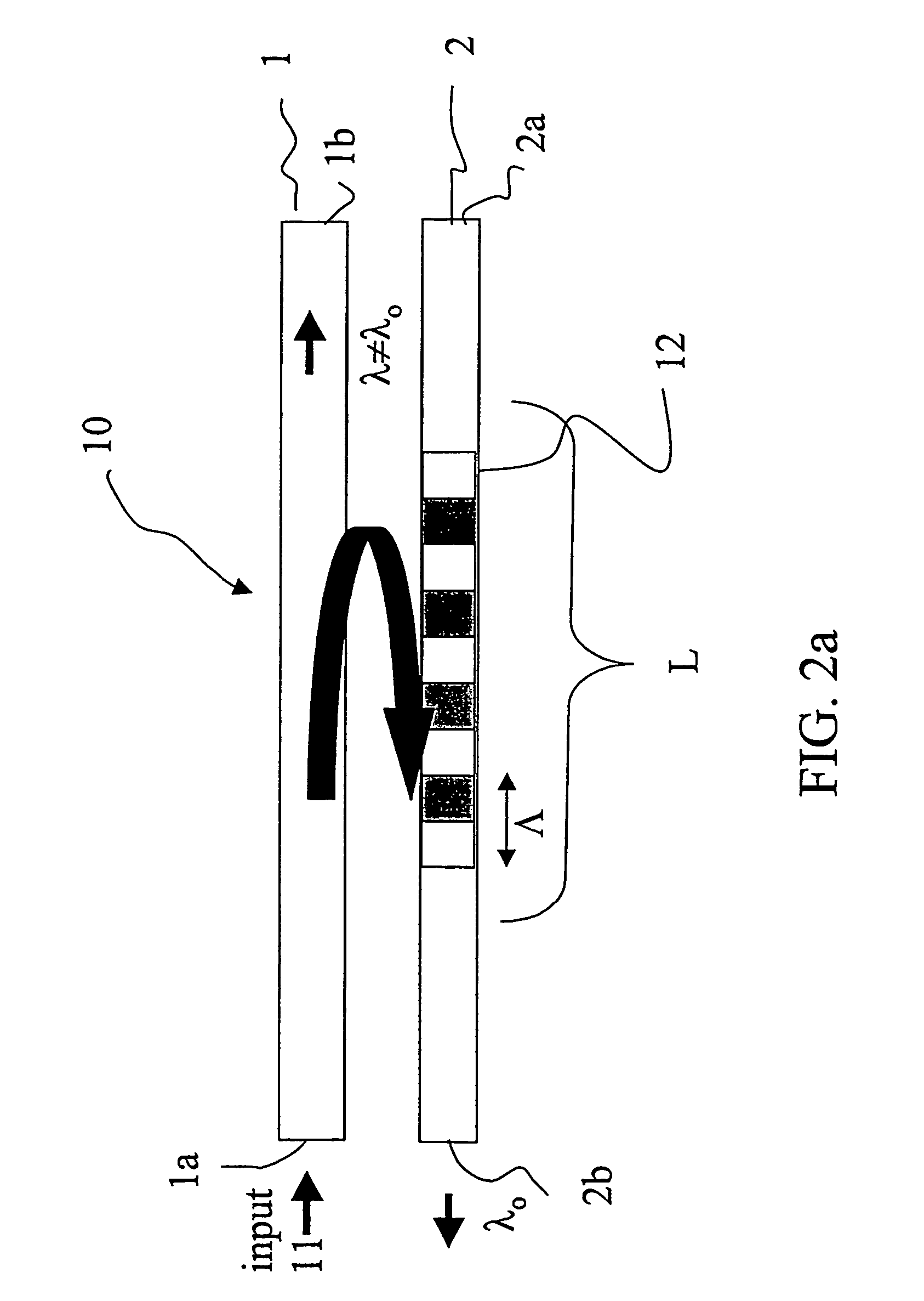
[0084]The grating 12 is realized on the upper core 8 and has a period Λ=47,805 μm for a total length of about 5,76 cm (1205 periods). In particular, the grating is realized on the top portion of the core of the output waveguide, ...
PUM
| Property | Measurement | Unit |
|---|---|---|
| refractive index | aaaaa | aaaaa |
| wavelength | aaaaa | aaaaa |
| wavelengths | aaaaa | aaaaa |
Abstract
Description
Claims
Application Information