Apparatus for assisting steering of vehicle when backing

Inactive Publication Date: 2007-11-13
TOYOTA IND CORP
View PDF28 Cites 100 Cited by
  • Summary
  • Abstract
  • Description
  • Claims
  • Application Information

AI Technical Summary

Benefits of technology

[0009]Accordingly, it is an objective of the present invention to provide an apparatus for assisting steering of vehicle when vehicle is moving backward, which provides guidance on a monitor s

Problems solved by technology

However, the superimposed path 41 does not give the driver information necessary for judging how he should manipulate the steering wheel.
Howeve

Method used


Image

  • Apparatus for assisting steering of vehicle when backing
  • Apparatus for assisting steering of vehicle when backing
  • Apparatus for assisting steering of vehicle when backing

Examples


first embodiment

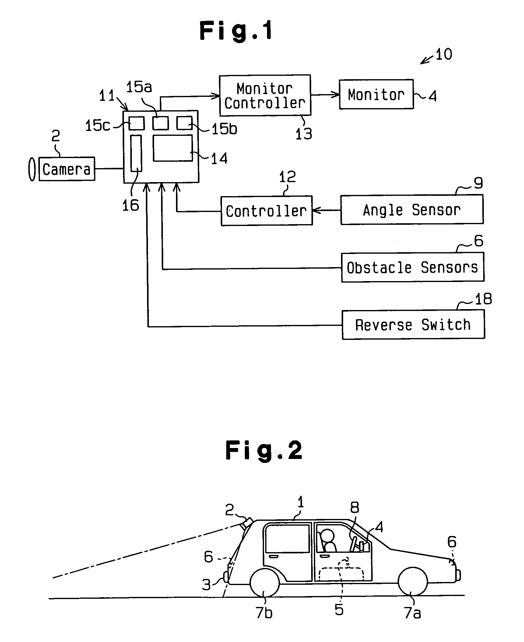
[0042]A first embodiment according to the present invention will now be described with reference to FIGS. 1 to 13. As shown in FIG. 2, a vehicle 1 has a monochrome camera 2 for capturing the view from the vehicle rear. A rear bumper 3 is at the nearest end of the view of the camera 2. The distance between the bumper 3 and the farthest extend of the camera view is greater than the length of the vehicle 1.

[0043]A monitor 4 for showing the image captured by the camera 2 is located in the passenger compartment of the vehicle 1. The monitor 4 is a color liquid crystal display and is also used as the monitor of a navigation system. The monitor 4 is normally used as the navigation system monitor. When a shift lever 5 is shifted to a reverse position, the monitor 4 shows the image captured by the camera 2.

[0044]Obstruction sensing means, which are obstruction sensors 6, are arranged in the corners of the vehicle 1. The obstruction sensors 6 are, for example, conventional sensors such as ult...

second embodiment

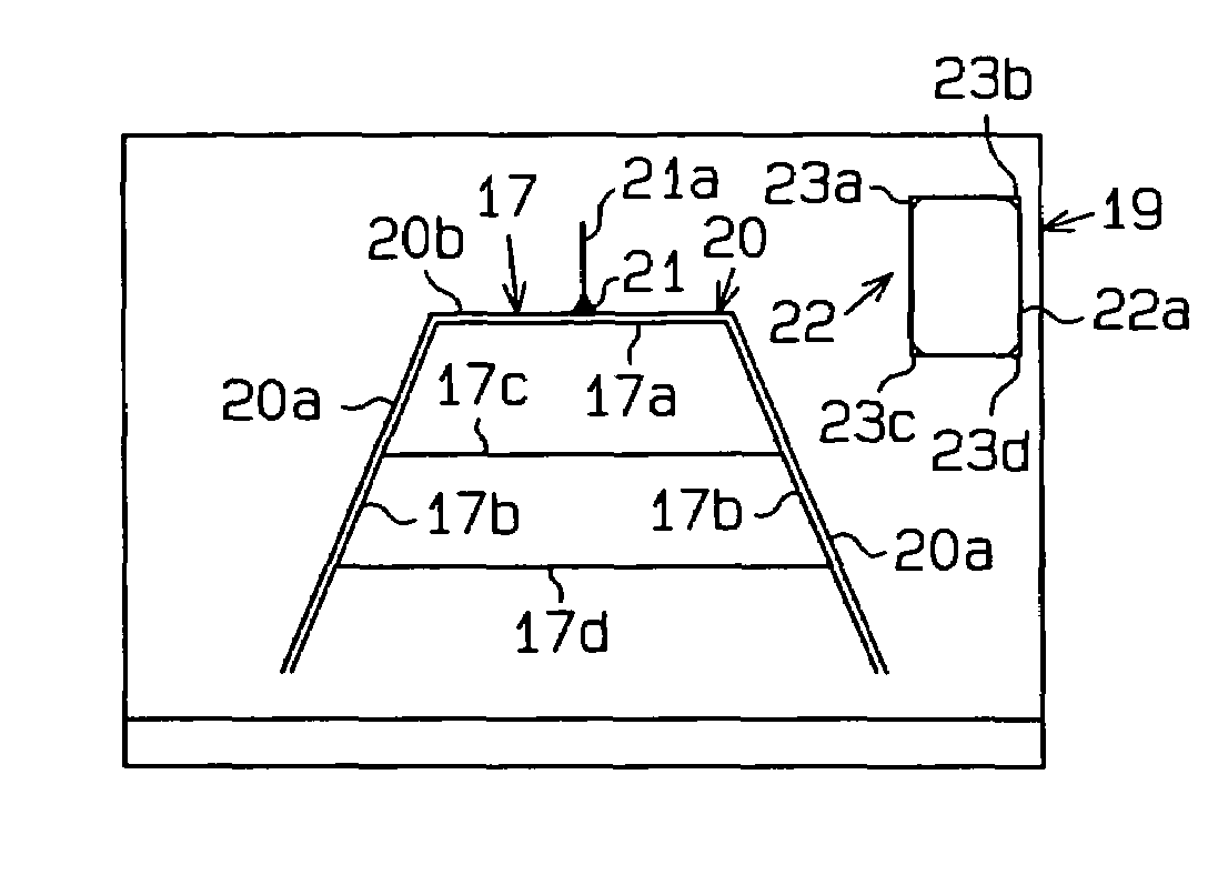
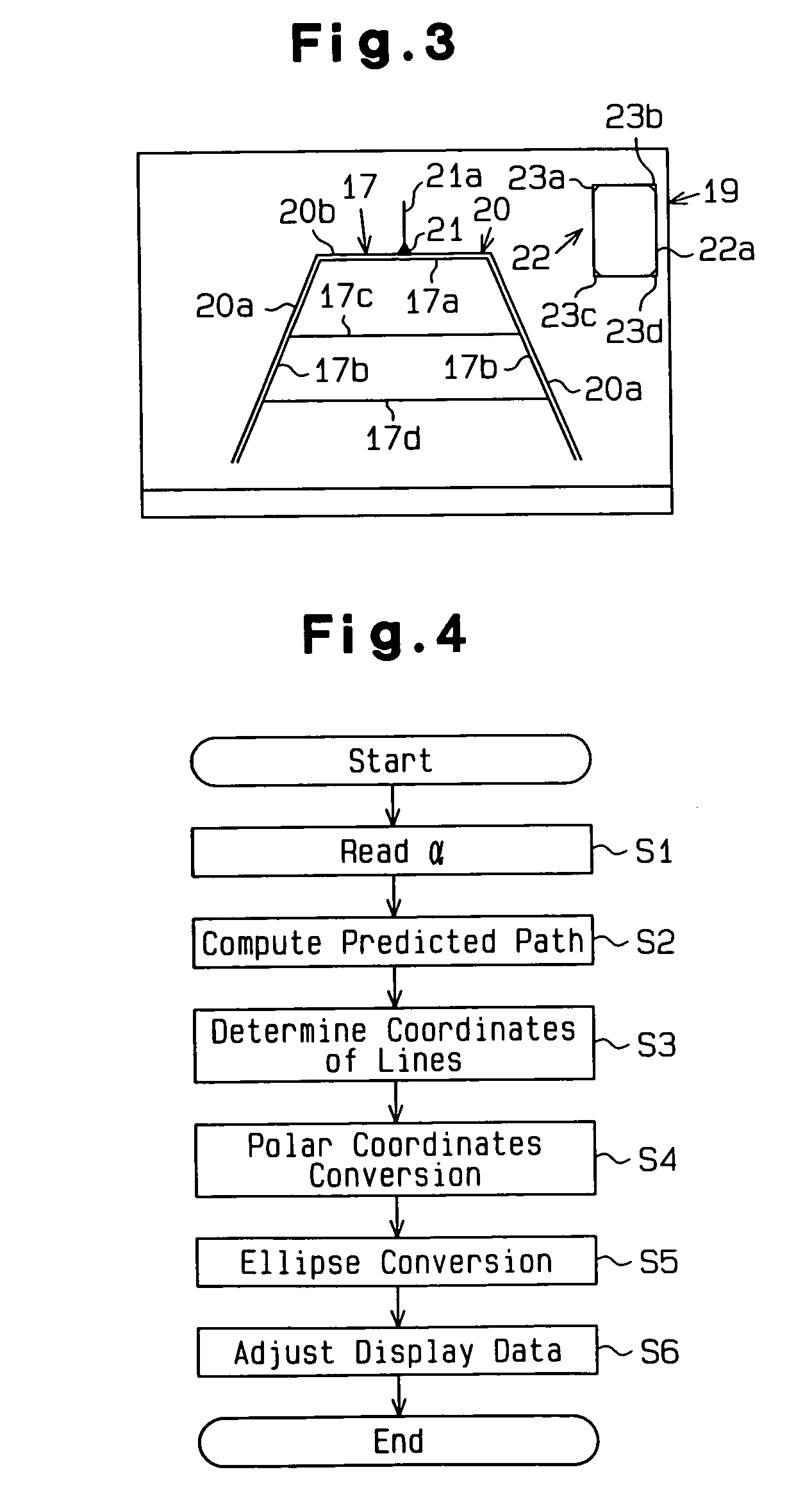
[0132]As in the second embodiment, the CPU 14 executes steps S14, S15 and S16. Accordingly, the monitor controller 13 superimposes the guide frame 17 on the image of the view from the rear of the vehicle on the screen 19 of the monitor 4.

[0133]The third embodiment has the same advantages as the second embodiment except the advantage (18). Further, the third embodiment has the following advantages.

[0134](19) The predicted path is corrected in accordance not only with the current steering speed Vθ but also with the vehicle speed v. Therefore, the guide frame 17 is displayed at a proper location regardless whether the steering wheel 8 is being rotated. Even if the vehicle speed v is changed, the guide frame 17 is properly adjusted.

[0135](20) The correction value is obtained by multiplying the steering amount C per unit distance traveled by the vehicle with the predetermined coefficient. The coefficient is previously obtained through tests. The coefficient is therefore easily and accura...

fourth embodiment

[0137]As shown in FIGS. 20A to 20C, the apparatus of the fourth embodiment has two markers 27a, 27b for parallel parking. The marker 27a is used when parallel parking a vehicle to a parking space located to the left and behind the vehicle. The marker 27b is used when parallel parking a vehicle to a parking space located to the right and behind the vehicle. The marker 27a is located on a line extended from the right side of the vehicle 1. The marker 27a is separated from the rear end of the vehicle 1 (the rear bumper 3) by a predetermined distance. The marker 27b is located on a line extended from the left side of the vehicle 1. The marker 27b is separated from the rear end of the vehicle 1 (the rear bumper 3) by a predetermined distance. Auxiliary lines 28 extend rearward from the markers 27a, 27b. The auxiliary lines 28 extend from the side lines of the vehicle 1 and are aligned with side lines 29, which extend between the markers 27a, 27b and the bumper 3. When a parking space is ...


PUM


Abstract

A steering assist apparatus that assists a driver when backing a vehicle in an S-shaped path or parallel parking. The apparatus displays guidance marking on a monitor screen and the driver refers to the guidance marking, which permits the driver to easily back the vehicle to a desired position. The apparatus includes a camera, a monitor, an angle sensor, obstacle sensors, an image processing unit, a controller and a monitor controller. The image processing unit computes the predicted path of the vehicle at the current wheel angle. The monitor shows an image captured by the camera. The image processing unit generates data representing a guidance marking based on the predicted path and superimposes the marking on the monitor screen. The location of the marking on the screen is determined based on the current wheel angle. The marking represents part of the predicted path. Specifically, the marking matches the width of the vehicle. In the monitor screen, a marking is separated from the rear bumper of the vehicle by a distance corresponding to the wheelbase of the vehicle.

Description

BACKGROUND OF THE INVENTION[0001]The present invention relates to an apparatus for assisting steering when a vehicle is moving backward. More specifically, the present invention relates to a steering assist apparatus that includes a camera for capturing the view from the rear and a monitor for displaying the captured view along with marking for assisting the driver.[0002]In the prior art, apparatuses for showing the view from the rear of a vehicle have been proposed. Such an apparatus allows the driver to see the view from the vehicle rear without actually turning around. Japanese Examined Patent Publication No. 2-36417 discloses a rear monitoring apparatus, which includes a video camera for capturing view from the rear of the vehicle, a video monitor for showing the captured view and a sensor for outputting signals representing the angle of vehicle wheels. The apparatus generates marker signals based on signals from the wheel angle sensor and superimposes a marker on the video moni...

Claims


Application Information

Patent Timeline
IPC IPC(8): H04N7/00H04N7/18G01S15/931B60R1/00B60R21/00G01S15/02G01S15/86G08G1/16
CPCB60R1/00B62D15/0275B62D15/028G01S15/025G01S15/931H04N7/183B60R2300/301B60R2300/302B60R2300/305B60R2300/806G01S2015/935B60R2300/8093G01S15/86
Inventor ASAHI, GOROKURIYA, HISASHIUSHINO, MASASHIKIMURA, TOMIOTERAMURA, KOUSUKESHIMAZAKI, KAZUNORIHATTORI, KANJIYAMADA, SATOSHI
Owner TOYOTA IND CORP
Why Eureka
Try Eureka