Application of intermediate wavelength band spectroscopic ellipsometry to in-situ real time fabrication of multiple layer alternating high/low refractive index filters

a technology of high/low refractive index and spectroscopic ellipsometry, which is applied in the direction of optical radiation measurement, instruments, measurement devices, etc., can solve the problems of insufficient transmission extrema turning point data, difficult to measure ellipsometric deltas of 0.0 or 180 degrees, and insufficient data for reliable data. , to achieve the effect of improving fabrication precision

Inactive Publication Date: 2007-11-13
J A WOOLLAM CO
View PDF7 Cites 11 Cited by
  • Summary
  • Abstract
  • Description
  • Claims
  • Application Information

AI Technical Summary

Benefits of technology

[0029]Presently, where quarter-wavelength optical thickness layers are being formed, Transmission Intensity Extrema Turning Point vs. Layer Number data is the primary approach utilized during fabrication of multiple layer Filters to provide generally good insight as to when to change from deposition of high to low, and low to high refractive index materials. However, where other than quarter-wavelength optical thickness layers are being formed said transmission extrema turning point data is often not sufficient to provide reliable data upon which a decision can be based. It is in that light that the disclosed invention teaches supplementing said conventional Transmission Intensity Extrema Turning Point vs. Layer Number data, with ellipsometric DELTA vs. wavelength data, to improve fabrication precision.
[0030]It should be appreciated that the disclosed invention methodology can, however, be applied alone, (ie. not in supplemental combination with conventional Transmission Intensity Extrema Turning Point vs. Layer Number data). The disclosed invention teaches use of ell

Problems solved by technology

A problem in applying rotating polarizer or rotating analyzer ellipsometer systems, however, is that ellipsometric DELTA's of 0.0 or 180 degrees are very difficult to measure therewith out use of means such as the J.A. Woollam Co.
A problem with this approach is that in some physical thickness and/or wavelength ranges said Intensity Transmission “extrema” turning point data ca

Method used


Image

  • Application of intermediate wavelength band spectroscopic ellipsometry to in-situ real time fabrication of multiple layer alternating high/low refractive index filters
  • Application of intermediate wavelength band spectroscopic ellipsometry to in-situ real time fabrication of multiple layer alternating high/low refractive index filters
  • Application of intermediate wavelength band spectroscopic ellipsometry to in-situ real time fabrication of multiple layer alternating high/low refractive index filters

Examples


Embodiment Construction

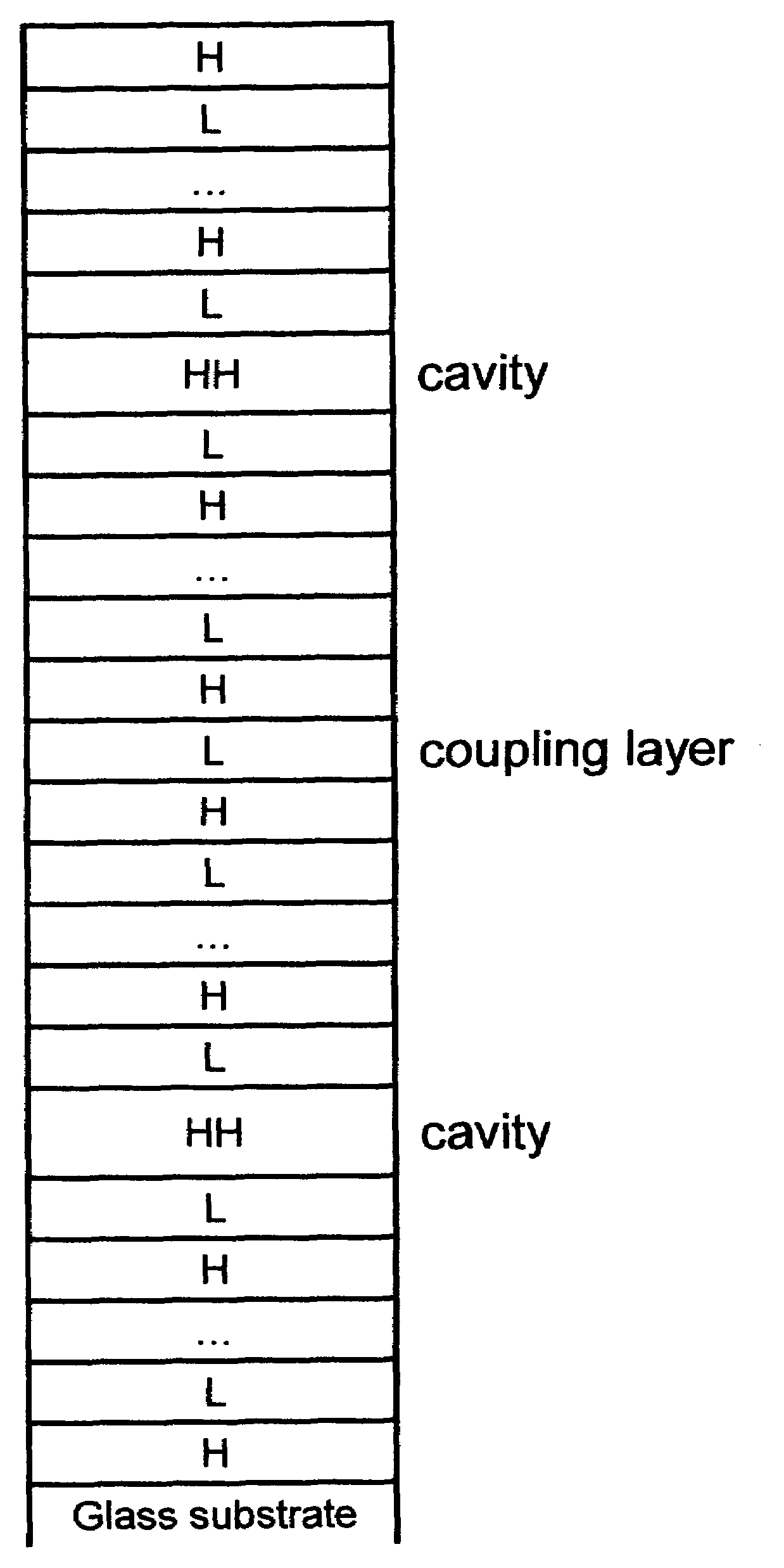
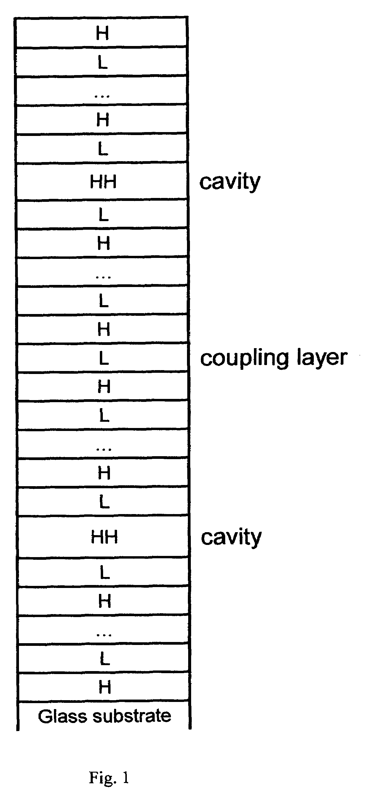
[0131]Turning now to FIG. 1, it should be appreciated that a schematic of a demonstrative 2-cavity all dielectric narrow Band-Pass optical filter structure is shown.

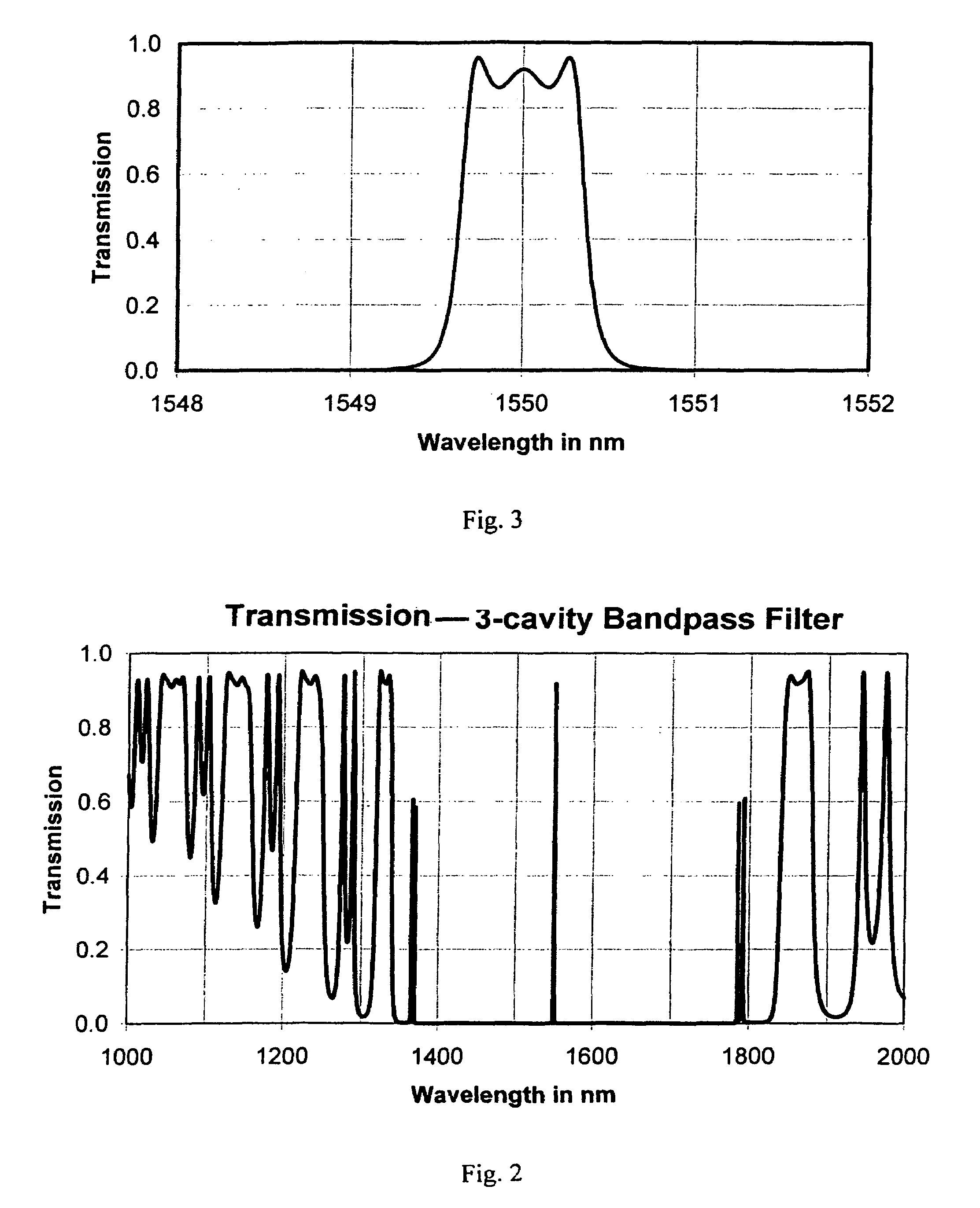
[0132]FIG. 2 shows the Transmission characteristic for a 3-cavity narrow Band-Pass optical filter (fabricated similar to the 2-cavity system shown in FIG. 1), over a broad range of 1000 to 2000 nm. FIG. 3 shows the Transmission characteristic for the 3-cavity narrow Band-Pass optical filter over an intermediate wavelength range of 1548 to 1552 nm.

[0133](Note that FIGS. 2 and 3 can be considered demonstrative of fabricatable stacked layer Band-Reject Filter characteristics as well, if the “Y” axis is labeled Reflection or Rejection instead of Transmission, and it is to be understood that the disclosed invention is similarly applicable to fabrication monitor / control of both Band-Pass and Band-Reject as well as to Varied Attenuation vs. Wavelength stacked layer Filters. The major distinction being that Reflection ellipsomet...


PUM


Abstract

Disclosed is application of oblique angle of incidence, reflection and/or transmission mode spectroscopic ellipsometry PSI and/or DELTA, (including combinations thereof and/or mathematical equivalents), vs. wavelength data over an intermediate wavelength band range around a pass or reject band, to monitor and/or control fabrication of multiple layer high/low refractive index band-pass, band-reject and varied attenuation vs. wavelength thin film interference filters, either alone or in combination with transmissive non-ellipsometric electromagnetic beam turning point vs. layer data obtained at an essentially normal angle of incidence.

Description

[0001]This Application is a CIP of Allowed applications Ser. No. 10 / 194,881, Filed Jul. 15, 2002 now U.S. Pat. No. 6,940,595; and of Ser. No. 09 / 916,836 filed Jul. 27, 2001 now U.S. Pat. No. 6,636,309 and therevia Claims benefit of Provisional Application Ser. No. 60 / 305,535 Filed Jul. 14, 2001.TECHNICAL FIELD[0002]The disclosed invention relates to application of Intermediate Wavelength Band Ellipsometry to in-situ real-time monitoring and / or process control; and more precisely to the monitoring and / or controlling of the fabrication of multiple layer high / low refractive index Band-Pass, Band-Reject or Varied Attenuation vs. Wavelength filters comprising use of oblique angle-of-incidence Spectroscopic Ellipsometric Parameter vs. Wavelength data determined over wavelength range(s) in which reflectivity and / or transmisivity is relatively constant. Said method is optionally enhanced by combination with, or compliments use of conventional non-ellipsometric transmission intensity extrema...

Claims


Application Information

Patent Timeline
IPC IPC(8): G01J4/00
CPCG01N21/211G02B5/288G02B5/285G01N2021/213
Inventor JOHS, BLAINE D.HALE, JEFFREY S.WOOLLAM, JOHN A.HERZINGER, CRAIG M.
Owner J A WOOLLAM CO
Why Eureka
Try Eureka