Concentric holdown connection

a technology of concentration hold and connection, applied in the direction of buildings, buildings, constructions, etc., can solve the problems of failure of connection, damage to buildings, and difficulty in resisting compression loads, so as to reduce the standoff distance, reduce the racking effect, and reduce the effect of the standoff distan

Active Publication Date: 2007-11-20
SIMPSON STRONG TIE
View PDF78 Cites 33 Cited by
  • Summary
  • Abstract
  • Description
  • Claims
  • Application Information

AI Technical Summary

Benefits of technology

[0031]The combination member has a base dimensioned and formed for engaging a substantial portion of the seat portion of the holdown connector and has a much greater thickness than the washers used in most holdown connectors and has a greater resistance to bending than standard washers. This bending resistance keeps the load evenly distributed over the base of the combination member and the seat of the holdown connector and more effectively transfers the load from the seat to the load receiving portions or straps fastened to the held building structural member.
[0049]A feature of the present invention is the fact that deflection of the holdown connector is minimized during design uplift loads. The unexpected ability of the holdown connector to resist deflection under upward loads is thought to be due in part to the cold form bending of the holdown into the compound curve discussed above. Cold form bending hardens the steel and thus makes the steel more resistant to unbending during upward loads. Thus deflection is decreased and pursuant to many building code requirements, greater loads on the holdown connector may be achieved before the code dictated deflection occurs.

Problems solved by technology

Early holdowns and even most holdowns in use today are formed so that there is a short but deleterious lateral distance between the load force applied by the held member and the resistance force applied by the holding member causing an eccentric loading.
These upward forces, if unrestrained, would quickly bend a prior art holdown connector seat into the shape of the letter “U” and crush the cross grain wood mud sill members when the weight of the building crashes back down on the mud sill resulting in failure of the connection and possibly leading to the destruction of the building.
The problem with the U-shaped seat connector taught by U.S. Pat. No. 5,979,130, however, is the fact that they are problematical for resisting compression loads.
The compression loads are exerted on a very small surface area which results in crushing the mud sill instead of being distributed over a large area.
Channeling forces through a right angle bend is clearly the worst possible condition.
Failure of prior art holdown connectors is often at the right angle bend between the seat and the upright members or at the anchor bolt opening in the seat.
The work done by others in the field to improve the ability of concentric holdowns to resist huge upward forces due to earthquakes and high winds such as hurricanes and tornadoes generally resulted in raising the held column member needlessly high above the foundation member.
Part of the elevation distances, in prior art holdown connectors, may be shortened by predrilling bores in the end of the wood held member to receive the nut and anchor member, but this reduces the cross sectional area of the wood held member and thus the ability of the wood held member to resist large compression loads imposed in earthquake incidents.
With such a large opening, applicant expected the seat to fail at the large opening.
Instead, failure occurred in one of the strap members at a point well above the donut-like combination member.
This certainly could be a factor in achieving a higher load, but a ⅛″ difference in bend radius is not all that much and does not explain the unexpectedly high load rating.
Bending metal at too sharp an angle sets up stresses in the metal where failure often occurs.
Obviously some cold working of the metal occurs in the process of forming of the metal around the donut-like forming member which renders the metal in the holdown member harder and much more difficult to straighten out once the compound curve has been formed in the metal.

Method used


Image

  • Concentric holdown connection
  • Concentric holdown connection
  • Concentric holdown connection

Examples


Embodiment Construction

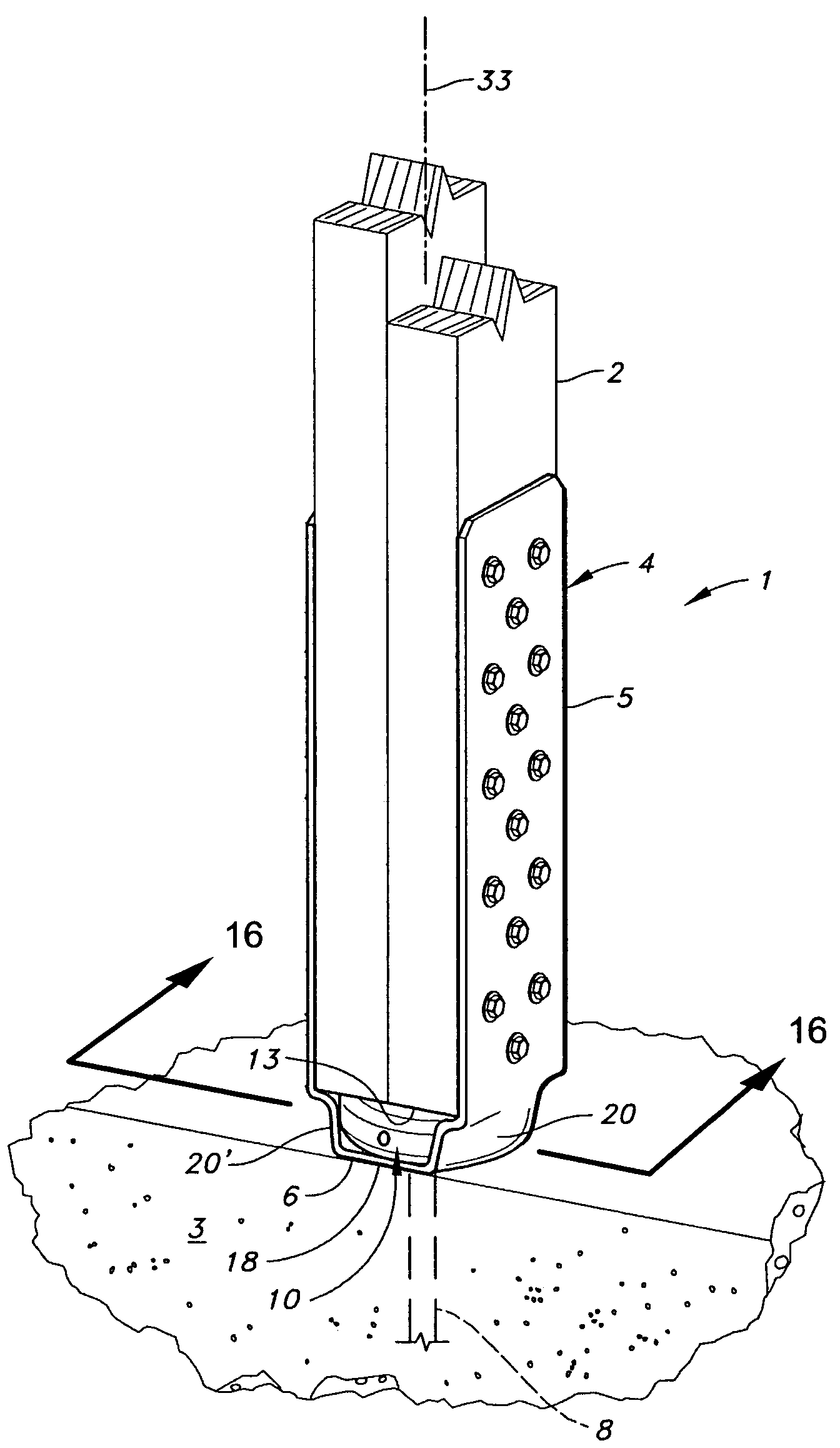
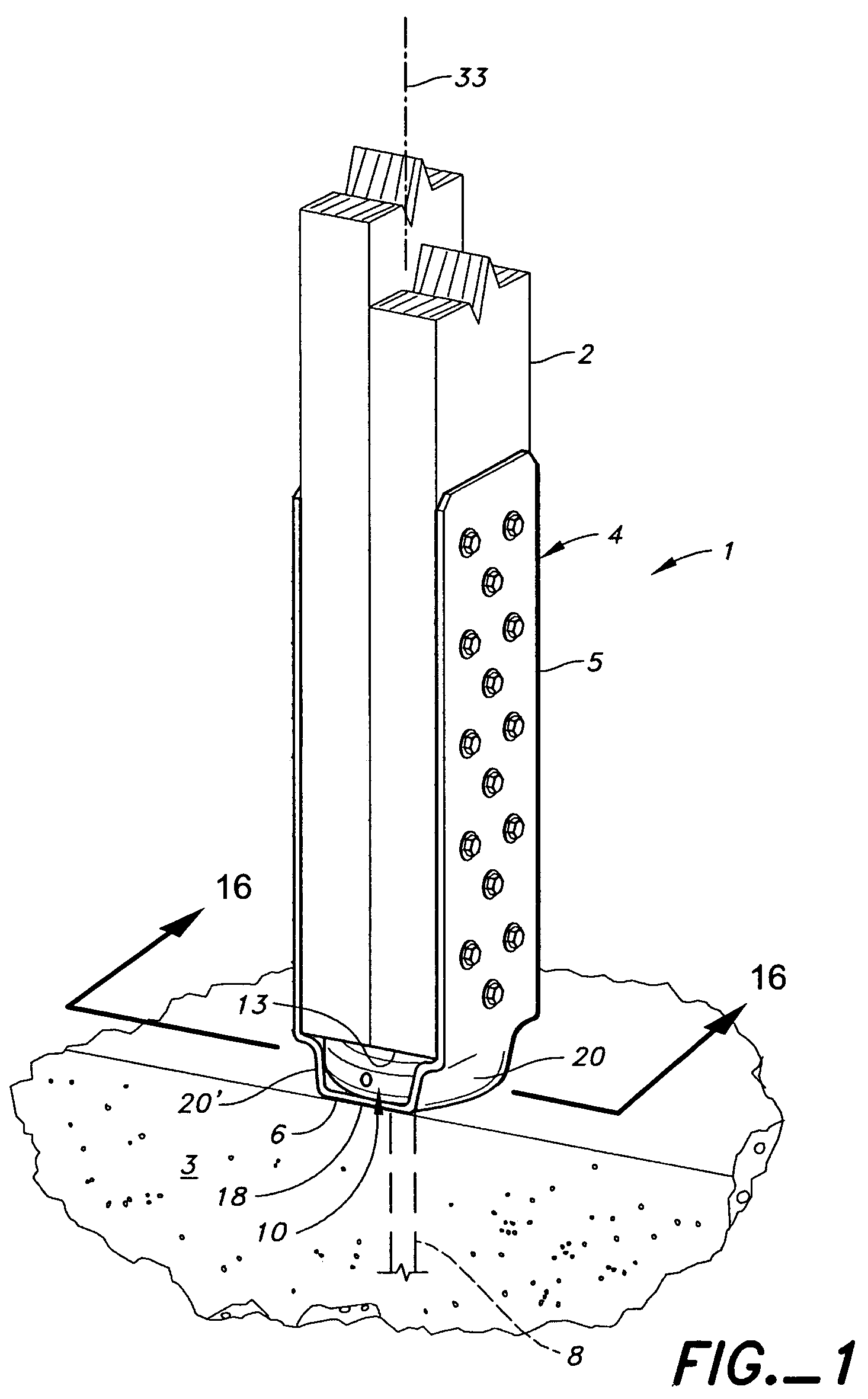
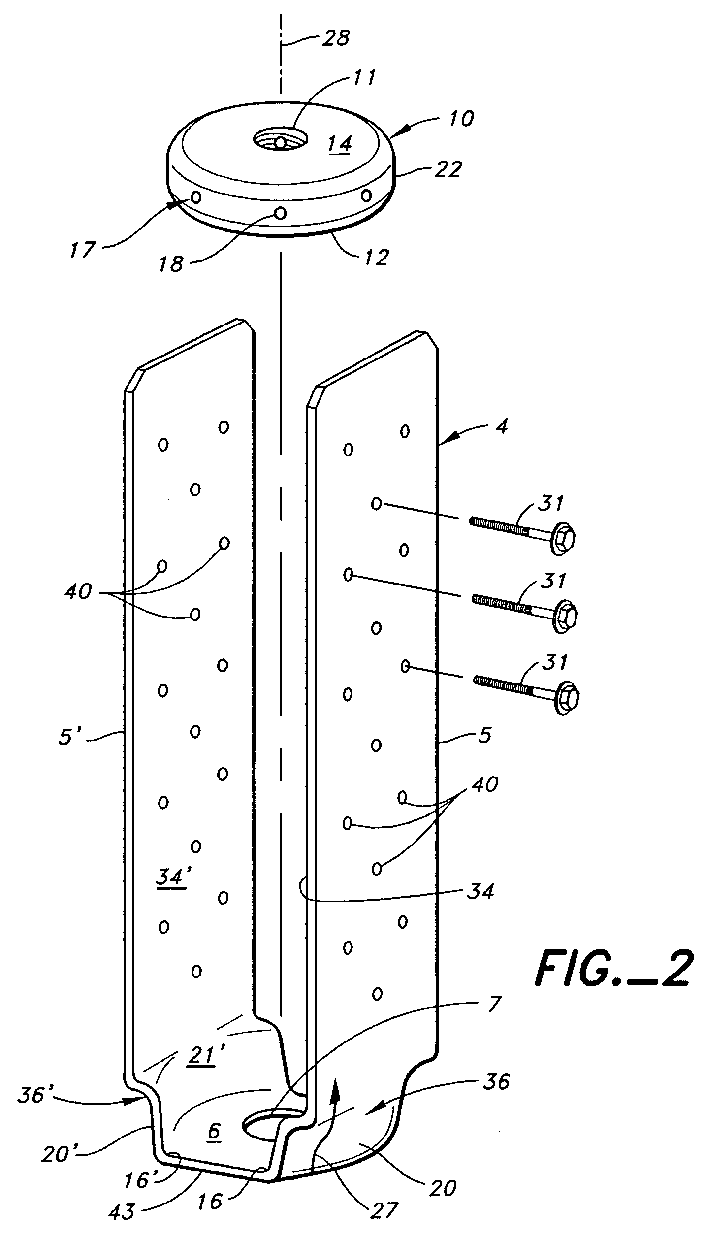
[0081]As stated in the background of the invention above, Applicant's initial purpose in providing the donut combination member was to reduce the stand off distance of the bottom of the wood column member above the seat of the holdown member; the so called “tower effect”. This objective was reached, but a much more unexpected achievement was obtained; viz., the concentric holdown connection was able to achieve a much higher load value.

[0082]To understand this achievement, it must first be understood that load ratings of holdown members in some jurisdictions such as Los Angeles, Calif. which is an elevated risk earthquake area, are based on the load that can be held before the sheet metal connector elongates in the direction of the load force or deflects ¼″. Applicant found that his concentric holdown using the donut combination member in a 7 gauge holdown with straps was able to achieve a load of 45,030 pounds before exceeding the 0.025″ deflection criteria. This was more than twice...


PUM


Abstract

A concentric holdown connection joining a held building structural member to a holding building structural member including a holdown connector having at least one upright portion operably connected to the held building structural member and a seat portion. A combination member having a threaded opening therethrough connects the holdown member to a threaded anchor member connected to the holding building structural member. In a preferred form the combination member has a donut-like configuration.

Description

BACKGROUND[0001]This invention relates to a concentric holdown connection for anchoring a first building structural member or held member to a second building structural member such as a foundation or holding member.[0002]The concentric holdown connection includes a holdown connector and an anchor member that is connected to the holding member, The holdown connector is attached to the held member with fasteners. The anchor member is threadably connected to a combination member seated on the holdown connector.[0003]Holdown connectors have been used for many years in building structures to strengthen the joints of wood frame members to better withstand such cataclysmic forces such as earthquakes, hurricanes, tornadoes, and floods. One of the primary uses of holdowns is in connecting the frame of a building to the concrete foundation.[0004]Early holdowns and even most holdowns in use today are formed so that there is a short but deleterious lateral distance between the load force appli...

Claims


Application Information

Patent Timeline
Patent Type & Authority Patents(United States)
IPC IPC(8): E04B1/21E04B1/38
CPCE04B1/24E04B1/26E04H12/2276E04H12/2238E04B2001/2451E04B2001/2684E04B2001/2463
Inventor LEEK, WILLIAM F.
Owner SIMPSON STRONG TIE
Why Eureka
Try Eureka