
Device for the variable actuation of the gas exchange valves of internal combustion engines, and method for operating one such device

a technology of gas exchange valve and variable actuation, which is applied in the direction of valve arrangement, machines/engines, mechanical equipment, etc., can solve the problems of difficult machined coulisses, insufficient contact between used housing materials, and noise and even damage, and achieves great accuracy

Active Publication Date: 2007-11-20
THYSSENKRUPP PRESTA TECCENTER AG
View PDF6 Cites 3 Cited by
  • Summary
  • Abstract
  • Description
  • Claims
  • Application Information

AI Technical Summary

Benefits of technology

[0007]Pursuant to the invention, the centers of rotation of the connecting links driven by the cams are restricted to the adjustment curve, that is they are guided by a positive fit. This ensures that the center of rotation of a connecting link cannot leave the adjustment curve, avoiding noise and damage which would result from it doing so. The design preferably realizes this feature by the fact that one or more connecting links are mounted on a cylindrical bolt on whose axis the centers of rotation lie, and that the axis of the bolt is restricted to the adjustment curve. If the active area on the driven element to which the radial cam of the connecting link transfers its motion is a circular cylinder, that is if it is formed by a roller, for example, it is possible to assume that the adjustment curve is arc-shaped and that its center coincides with the center of the circular cylindrical active area, that is, the roller.
[0010]A third embodiment of the inventive device involves guiding the bolt by a slide which is linearly adjustable in the control housing. This embodiment makes it possible to meet other, special space requirements. Relatively large contact areas are realized between the slide and the control housing, so that the strength properties of the housing material suffice in any case. The resulting adjustment curve is a straight line whose deviations from the shape of an arc are also taken up by play compensation elements.
[0014]The inventive device, including an adjusting motor or an adjusting device, can be separately provided for every valve of an engine, so that any combination of valve strokes or opening angles of the individual valves of an engine is possible, including the turning off of individual cylinders. However, as a rule common adjustment of several valves is provided. This applies especially for intake and exhaust valves of a cylinder in multiple-valve engines. For example, two intake valves can be actuated by a cam through a connecting link which has a radial cam for each valve. Since only one connecting link and only one bolt is present, both valves are adjusted together and in the same way. However, the inventive device also allows the common connecting link to have two different radial cams on it with the result of two different lifting curves on the two valves, despite the fact that they are adjusted together. This variant makes it possible, especially in the lowest load range, to open only one of the two valves. The special advantage of this possibility is that in the lowest load range it is possible to expose only very small cross sections which can be more precisely observed, if they are only exposed by one valve. In addition, opening only one of the intake valves makes it possible to produce swirl in the cylinder charge. The inventive device further expands the possibilities for producing different valve lifting curves for two intake or exhaust valves of a cylinder by the fact that two different cams and two connecting links are used with different radial cams. Nevertheless, the two valves can be adjusted together, since the two connecting links can be mounted on a common bolt.
[0019]The inventive solution has advantageously found an exact, low-wear adjustment device for gas exchange valves, which also works with great accuracy.

Problems solved by technology

First, the roller on the connecting link only lies against the courses when the gas forces and inertial forces of the valve train are correspondingly oriented and the roller is actually supported on the courses. If this is not the case, which can happen when an overspeed occurs, for example, then the non-positive connection is lost and a liftoff occurs, which causes noise and even damage when it comes back down. In addition, it is relatively difficult to machine the coulisses, which are segments of an inside cylinder and cannot be machined in a continuous manner, and the commonly used housing materials are insufficiently hard for the contact between the roller and the courses. There is a disadvantage concerning mounting, which is that the valve gear housing cannot be set on the cylinder head in completely premounted form.
However, the previous publications do not contain any teaching about how to construct the devices to realize such adjustment.
It is a common disadvantage of all devices that, due to manufacturing tolerances, as the valve strokes of the individual cylinders are reduced further for the purpose of controlling the load, the differences between the valve strokes of the individual cylinders become greater.

Method used


Image

  • Device for the variable actuation of the gas exchange valves of internal combustion engines, and method for operating one such device
  • Device for the variable actuation of the gas exchange valves of internal combustion engines, and method for operating one such device
  • Device for the variable actuation of the gas exchange valves of internal combustion engines, and method for operating one such device

Examples


Embodiment Construction

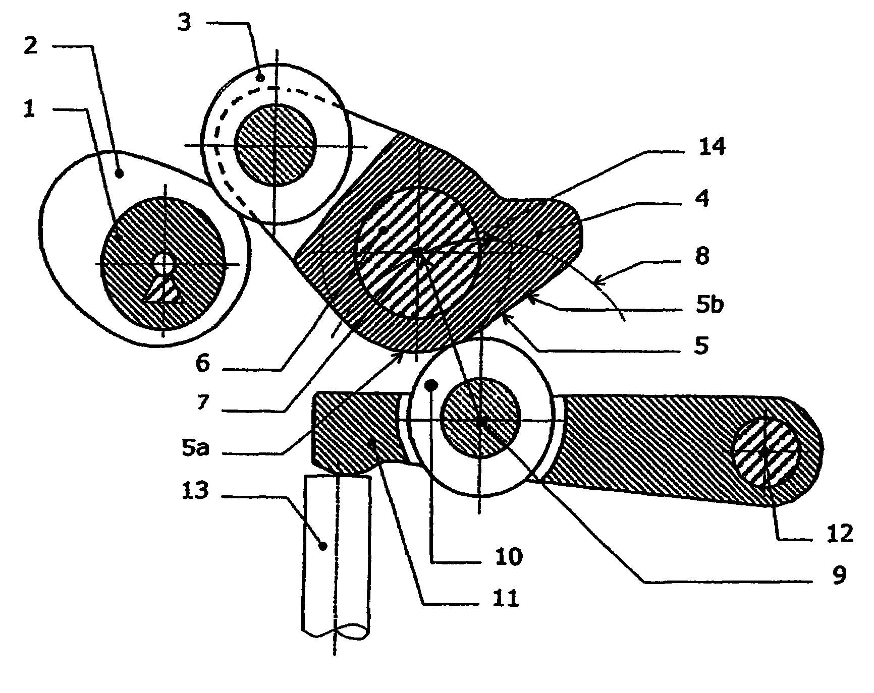
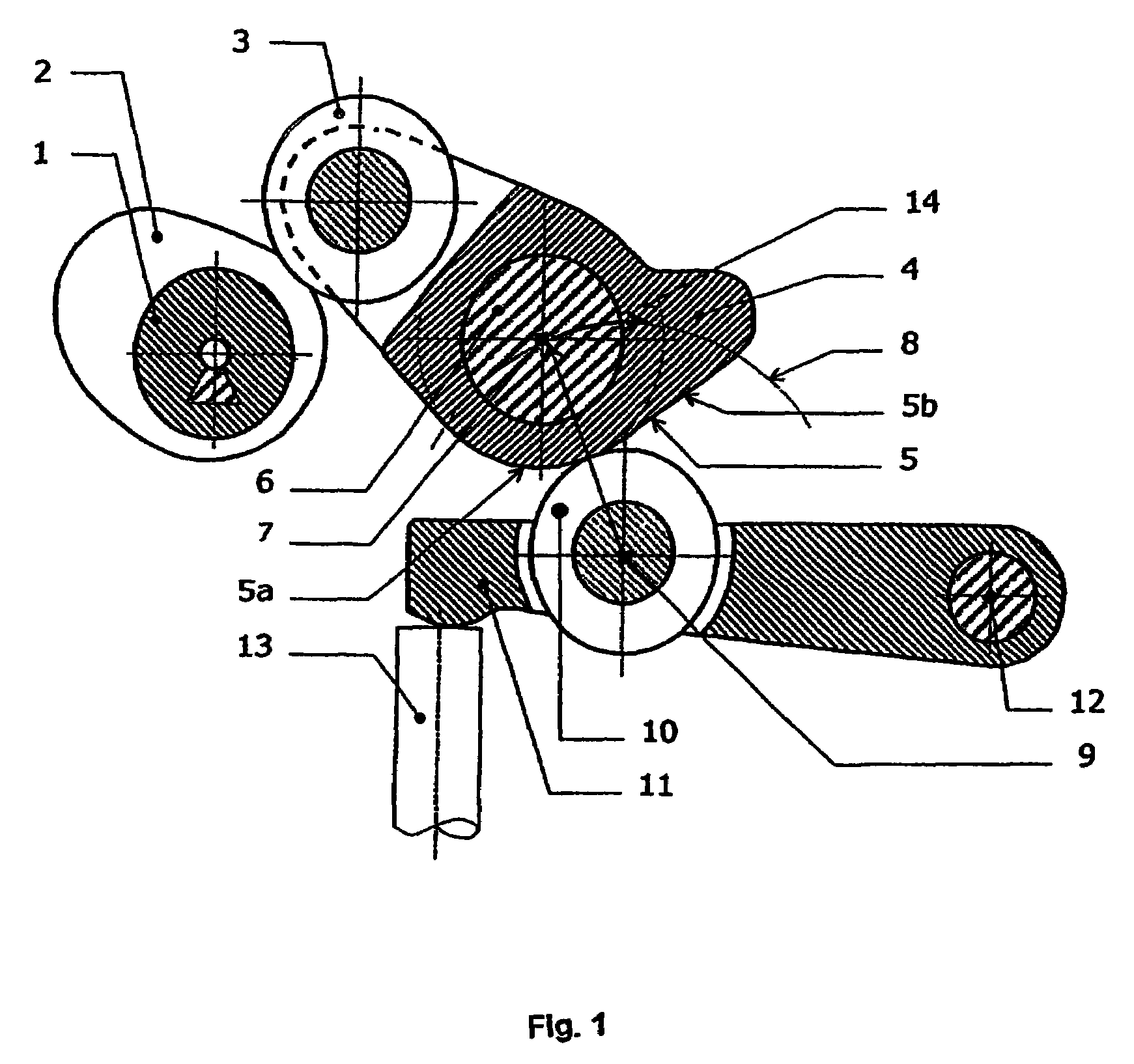
[0028]FIG. 1 shows a camshaft 1, which has a cam 2. The cam moves roller 3 at the end of connecting link 4. Connecting link 4 has a radial cam 5 which is composed of a rest area 5a and a lift area 5b. Connecting link 4 is mounted on a bolt 6 whose axis 7 is guided on an arc-shaped adjustment curve 8. The center of the arc-shaped adjustment curve 8 is on the axis 9 of the roller 10 of the driven element 11 which is supported through a joint 12 in a housing (not shown) and actuates valve 13. It can clearly be seen that adjustment of axis 7 on the adjustment curve 8 in the direction of arrow 14 has the consequence of reducing the opening angle and stroke of valve 13.

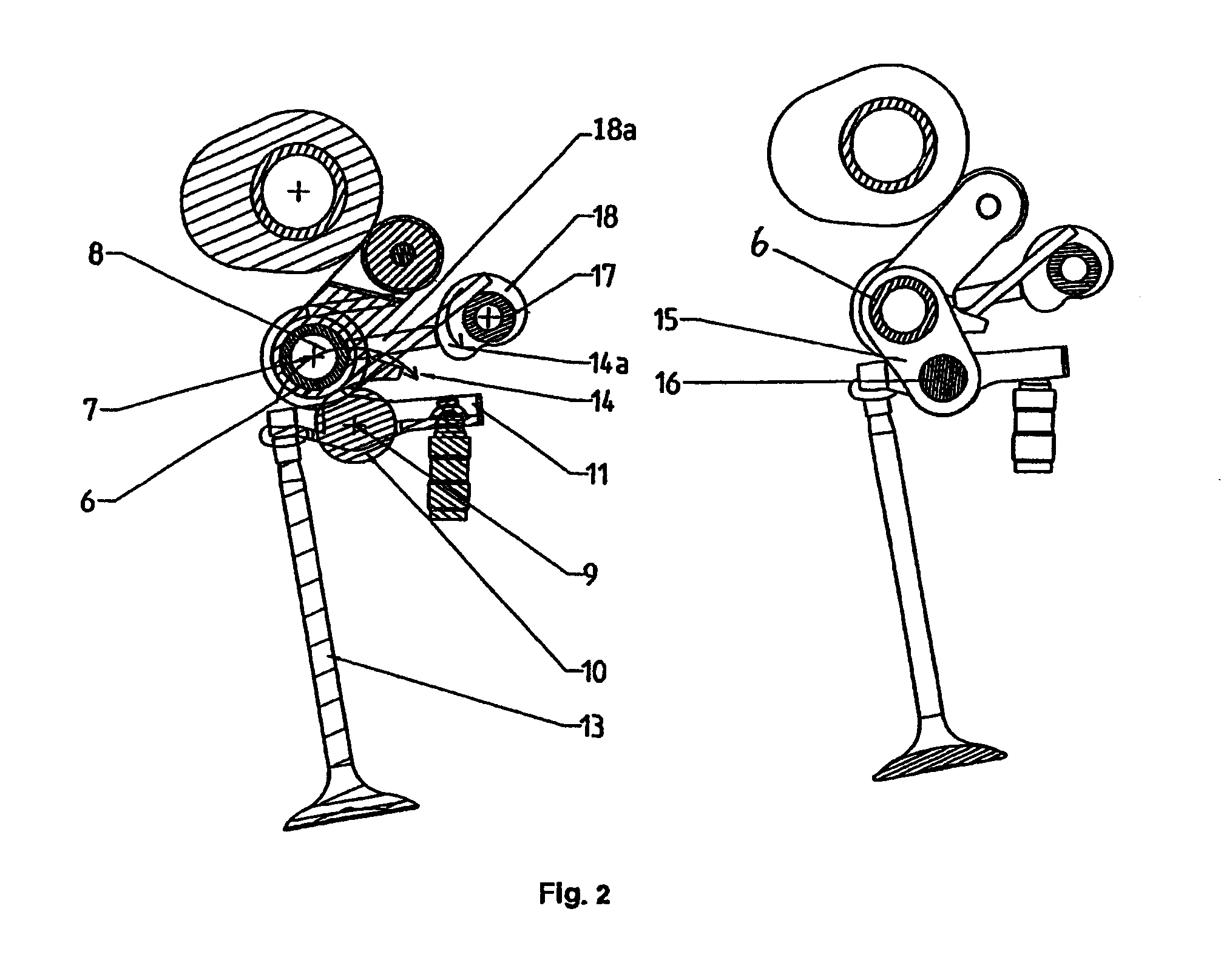
[0029]FIG. 2 shows an embodiment in which the bolt 6 or its axis 7 is guided on the arc-shaped adjustment curve 8 by positive connection to a pendulum support 15. Cylinder head-side joint 16 of pendulum support 15 or its axis coincides with the axis 9 of roller 10 of driven element 11. Adjusting shaft 17 holds cam disks 18,...


PUM


Abstract

The invention relates to a device for the variable actuation of gas exchange valves for internal combustion engines, wherein at least one cam (2) pertaining to a camshaft (1) mounted in a housing rotates according to the engine speed. The cam (2) first drives an intermediate member (4) which performs a clear oscillating, rotary movement and has a rotational axis (7) that can be displaced in the housing parallel to itself along a curve of displacement (8), said intermediate member comprising a control cam (5) having a lifting region (5b) and actuating an output member (11) that, in turn, actuates at least one valve (13). The aim of the invention is to enable one such device to be reliably controlled. To this end, the control cam (5) has a catch region (5a), and the intermediate member (4) is mounted on a bearing having an axis which corresponds to the rotational axis (7), said bearing being arranged in such a way that it is guided in a forced manner and can be displaced parallel to the curve of displacement (8, 28, 35), by means of an articulation (16, 24, 26) connected to the cylinder head or the housing or by a slide (34) that is guided in the housing in a positively locking manner. The invention also relates to a method for operating an internal combustion engine comprising a plurality of cylinders using at least one of the inventive devices.

Description

BACKGROUND OF THE INVENTION[0001]Such devices are used to control gas exchange valves in such a way, that it becomes possible to operate reciprocating engines without the throttle valve that would otherwise be necessary.[0002]Such a device is disclosed in DE 101 23 186 A1, for example. In this device, a rotating cam first drives a connecting link, which executes a pure oscillating rotary motion and carries a radial cam which is composed of a rest area and a lift area. The radial cam transfers the lifting curve necessary for actuation of the valve to the roller of a driven element similar to a cam follower which in turn actuates the valve. The desired different valve lifting curves are produced by the fact that the center of rotation of the connecting link is displaced on an arc-shaped path which is concentric to the roller of the driven element when it is in the position that it assumes when the valve is closed. The center of rotation is formed by a roller which is provided on the c...

Claims


Application Information

Patent Timeline
Patent Type & Authority Patents(United States)
IPC IPC(8): F01L1/34F01L13/00
CPCF01L13/0005F01L13/0063F01L2013/0068F01L2820/032F01L2105/00F01L2800/06F01L2800/13F01L2103/01F01L2303/01F01L2305/00
Inventor SCHON, HELMUTKELLER, KAI-UWEKUHN, PETERKOHNE, GORDONOBRIST, FRANKBUSCH, CHRISTIAN
Owner THYSSENKRUPP PRESTA TECCENTER AG
Learn More