Solid polymer electrolyte fuel cell stack

a solid polymer electrolyte and fuel cell technology, applied in the field of fuel cell stacks, can solve the problems of inefficiency in large size of the entire fuel cell stack, and inability to supply cooling water to the entire power generation surface, so as to achieve uniform and smooth cooling of power generation surface, and suppress the dimension in the height direction.

Inactive Publication Date: 2007-11-20
HONDA MOTOR CO LTD
View PDF18 Cites 5 Cited by
  • Summary
  • Abstract
  • Description
  • Claims
  • Application Information

AI Technical Summary

Benefits of technology

[0013]A general object of the present invention is to provide a fuel cell stack which makes it possible to suppress the dimension in the height direction of an entire fuel cell stack to be low, and cool the power generation surface uniformly and smoothly.

Problems solved by technology

As a result, the entire fuel cell stack has a considerably large size.
For this reason, it is impossible to supply the cooling water to the entire power generation surface.
It is feared that the power generation surface cannot be cooled efficiently.
That is, the cooling medium flow passage is lengthy, the large pressure loss is generated, and the temperature distribution arises in the separator surface.
However, the following inconvenience arises.
That is, the length of the fuel cell stack in the stacking direction is considerably lengthy, and it is impossible to uniformly supply the fuel gas to the respective fuel cell units.
That is, the assembling operation for the entire fuel cell is complicated, and the arrangement of the supply / discharge member for the fuel and the like is considerably complicated.
The supply / discharge member for the fuel and the like has a large size and a complicated structure, and the production cost is expensive.

Method used


Image

  • Solid polymer electrolyte fuel cell stack
  • Solid polymer electrolyte fuel cell stack
  • Solid polymer electrolyte fuel cell stack

Examples


first embodiment

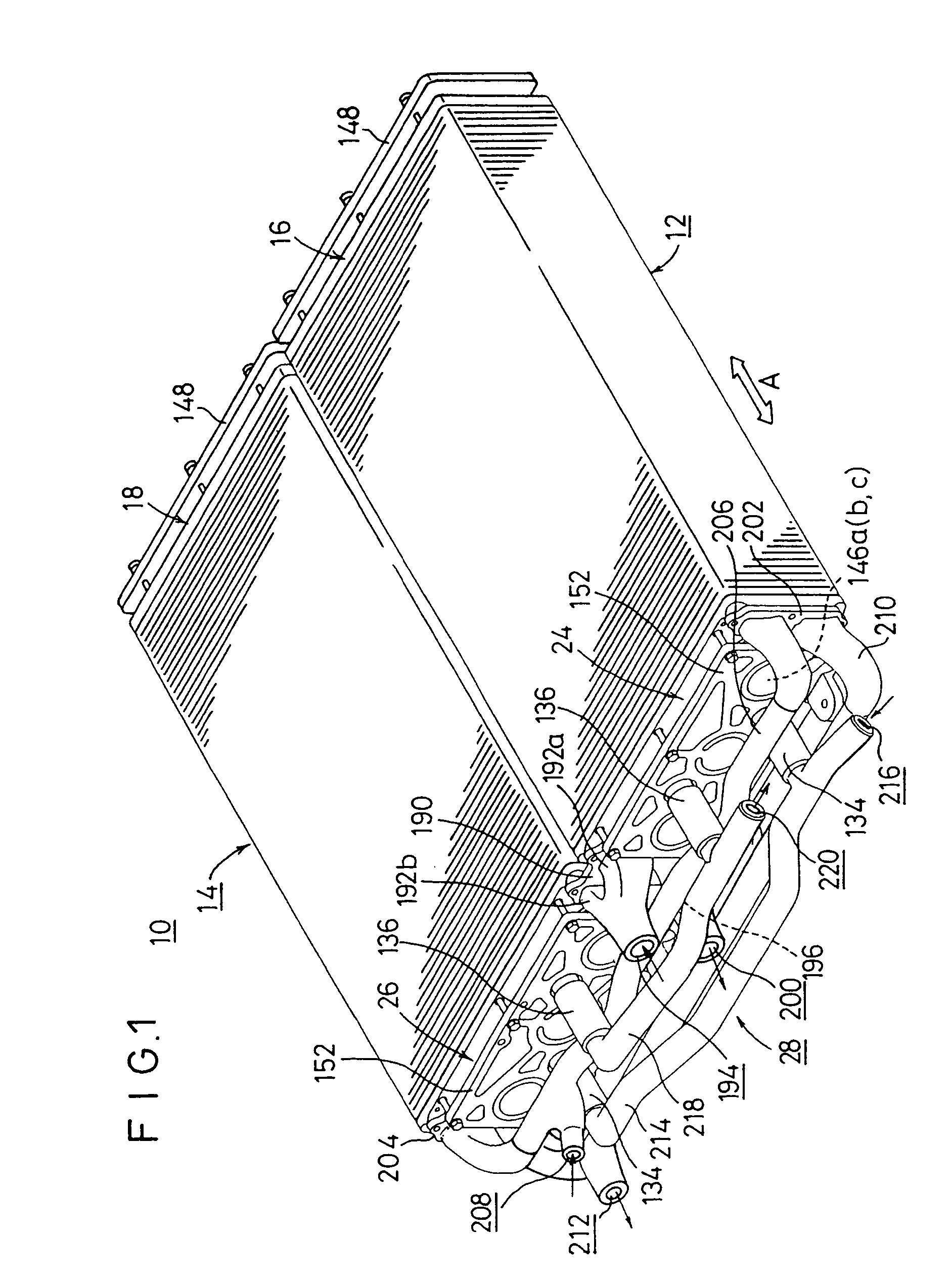
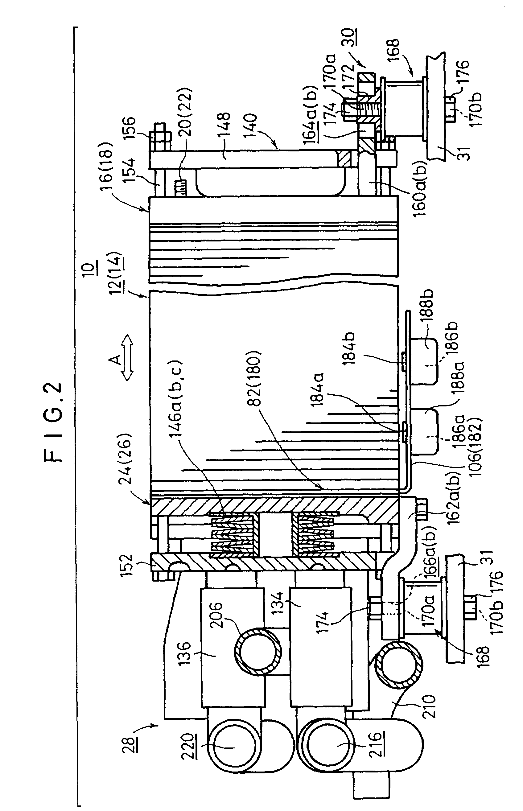
[0035]FIG. 1 shows a schematic perspective view illustrating a fuel cell system 10 into which fuel cell stacks according to the present invention is incorporated, and FIG. 2 shows a side view illustrating the fuel cell system 10.

[0036]The fuel cell system 10 comprises a first fuel cell stack 12 and a second fuel cell stack 14 which are arranged in parallel to one another in the horizontal direction (direction of the arrow A). A first electric power-deriving terminal 20 as a positive electrode, and a second electric power-deriving terminal 22 as a negative electrode are provided on first end plates 16, 18 which constitute vertical surfaces disposed at first ends on an identical side of the first and second fuel cell stacks 12, 14 respectively.

[0037]A piping mechanism 28, which is used to supply and discharge a fuel gas, an oxygen-containing gas, and a cooling medium with respect to the first and second fuel cell stacks 12, 14, is incorporated on a side of second end plates 24, 26 whi...

second embodiment

[0099]In the second embodiment constructed as described above, the air and the fuel gas are supplied to the oxygen-containing gas supply / discharge passage 138a and the fuel gas supply / discharge passage 138b from the lower portions at the both ends in the lateral direction in the fuel cell stack 240. The air is introduced into the first oxygen-containing gas flow passage grooves 62 in the surface 242a of the first separator 242, and it is moved in the direction of the antigravity while meandering in the horizontal direction. The air, which is not used, is discharged to the oxygen-containing gas outlet 56b via the second oxygen-containing gas flow passage grooves 65. The air is discharged from the upper portion at the both end in the lateral direction of the fuel cell stack 240.

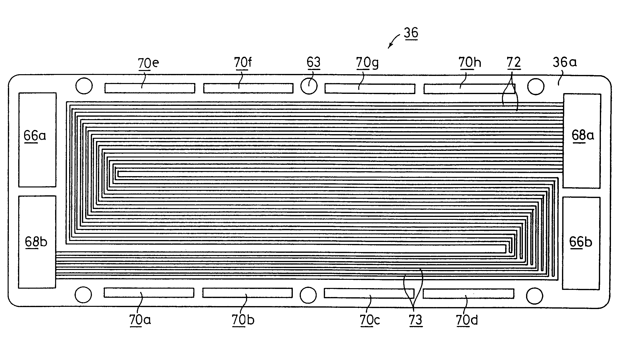
[0100]On the other hand, the fuel gas is introduced into the first fuel gas flow passage grooves 72 in the surface 244a of the second separator 244, and it is moved in the direction of the antigravity while mea...


PUM

PropertyMeasurementUnit
horizontal lengthaaaaaaaaaa
lengthaaaaaaaaaa
DC electric energyaaaaaaaaaa

Abstract

A fuel gas inlet, a fuel gas outlet, an oxygen-containing gas inlet, an oxygen-containing gas outlet, and other components, which are disposed at upper and lower portions at both ends in the lateral direction, are provided in a first fuel cell stack. A plurality of cooling medium inlets, a plurality of cooling medium outlets, and other components are provided at lower portions on the long side and at upper portions on the long side respectively. A cooling medium flows from the lower portions to the upper portions through cooling medium flow passages to cool the power generation surface smoothly and reliably.

Description

RELATED APPLICATIONS[0001]This application is a continuation application of U.S. Ser. No. 09 / 641,187 filed Aug. 17, 2000, now U.S. Pat. No. 6,613,470 which claims priority to Japanese Patent Application No. 11-247790, filed Sep. 1, 1999 in Japan, Japanese Patent Application No. 11-249830, filed Sep. 3, 1999 in Japan and Japanese Patent Application No. 2000-227413, filed Jul. 27, 2000 in Japan. The contents of the aforementioned applications are hereby incorporated by reference.BACKGROUND OF THE INVENTION[0002]1. Field of the Invention[0003]The present invention relates to a fuel cell stack comprising a plurality of fuel cell units each composed of a solid polymer ion exchange membrane interposed between an anode electrode and a cathode electrode, the plurality of fuel cell units being stacked in the horizontal direction with separators intervening therebetween.[0004]2. Description of the Related Art:[0005]For example, the solid polymer type fuel cell comprises a fuel cell unit inclu...

Claims


Application Information

Patent Timeline
Patent Type & Authority Patents(United States)
IPC IPC(8): H01M8/00H01M2/00H01M2/14H01M8/04H01M8/24H01M50/77
CPCH01M8/0258H01M8/04089H01M8/241H01M8/04029Y02E60/50H01M8/247H01M8/249H01M2300/0082H01M8/2483H01M8/0267H01M8/0263H01M8/2484
Inventor SUGITA, NARUTOSHIOSAO, NORIAKIUSHIO, TAKESHI
Owner HONDA MOTOR CO LTD
Why Eureka
Try Eureka