Methods and apparatus for reducing thermal noise

a technology of thermal noise and circuits, applied in the direction of noise figure or signal-to-noise ratio measurement, instruments, heat measurement, etc., can solve the problems of thermal noise being thermal noise is also sampled, and thermal noise will be present in the switch used for sampling operation or the amplifier used, so as to limit the bandwidth of a signal and contribute less noise to the signal

Active Publication Date: 2007-11-20
ANALOG DEVICES INC
View PDF17 Cites 15 Cited by
  • Summary
  • Abstract
  • Description
  • Claims
  • Application Information

AI Technical Summary

Problems solved by technology

One problem associated with sampling circuits, such as switched capacitor circuits, is that each time a signal is sampled, thermal noise is also sampled.
Thermal noise arises due to the random motion of free electrons in a conducting medium.
However, thermal noise will be present in the switch used for the sample operation or an amplifier used for the sample operation.
The sampled thermal noise introduces undesired disturbances into the sampled signal.
Although the capacitance of the sampling capacitor selected can be increased to reduce the sampled thermal noise, large capacitance is undesirable because larger capacitors in a sampling circuit consume more power and space.
In particular, the unity gain feedback of the amplifier in this configuration reduces the effective offset and low frequency noise during hold mode at inverting input 47.
However, larger sampling capacitors are undesirable because they increase the silicon area required for an integrated sampling circuit, thereby increasing the overall size of the circuit.
In addition, larger sampling capacitors require more power and are more difficult for the input to drive.

Method used


Image

  • Methods and apparatus for reducing thermal noise
  • Methods and apparatus for reducing thermal noise
  • Methods and apparatus for reducing thermal noise

Examples


Embodiment Construction

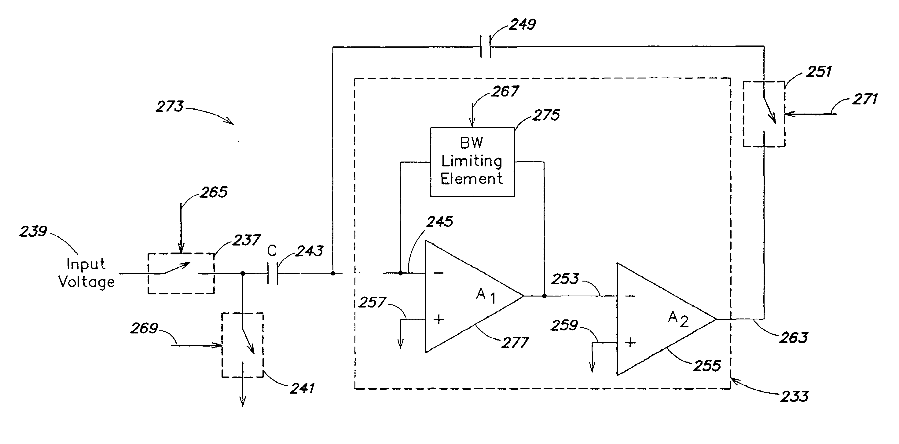
[0044]Applicant has appreciated that by implementing a circuit (e.g., a sampling circuit) such that the spectral density and the bandwidth of the thermal noise are determined by different factors, thermal noise integrated on a capacitor of the circuit may be reduced below kT / C. Specifically, if the spectral density and the bandwidth of the thermal noise are determined by different factors, for example because they are dominated by different elements of the circuit, the bandwidth and spectral density equations will contain terms (other than k, T, and C) that can be independently controlled and do not cancel when the integrated thermal noise power is computed. Thermal noise may also be reduced in circuits having non-capacitive storage elements (e.g., inductors) by implementing a circuit such that the spectral density and the bandwidth of the thermal noise are determined by different factors.

[0045]Embodiments of the invention relate to methods and apparatus for reducing the thermal noi...


PUM


Abstract

Methods and apparatus for reducing the thermal noise integrated on a storage element are disclosed. One embodiment of the invention is directed to a sampling circuit comprising a sampling capacitor to store a charge, the sampling capacitor being exposed to an ambient temperature. The sampling circuit further comprises circuitry to sample the charge onto the capacitor, wherein thermal noise is also sampled onto the capacitor, and wherein the circuitry is constructed such that the power of the thermal noise sampled onto the capacitor is less than the product of the ambient temperature and Boltzmann's constant divided by a capacitance of the sampling capacitor. Another embodiment of the invention is directed to a method of controlling thermal noise sampled onto a capacitor. The method comprises an act of independently controlling the spectral density of the thermal noise and / or the bandwidth of the thermal noise.

Description

CROSS-REFERENCE TO RELATED APPLICATION[0001]This application claims the benefit, under 35 U.S.C. §119(e), of the filing date of U.S. provisional application Ser. No. 60 / 564,386 entitled “Methods and Apparatus for Reducing the Thermal Noise in Sampling Circuits,” filed Apr. 21, 2004 and incorporated herein by reference.FIELD OF THE INVENTION[0002]The present invention is directed to the field of reducing thermal noise in circuits.DESCRIPTION OF THE RELATED ART[0003]One problem associated with sampling circuits, such as switched capacitor circuits, is that each time a signal is sampled, thermal noise is also sampled. Thermal noise arises due to the random motion of free electrons in a conducting medium. Each free electron inside the medium is in motion due to its thermal energy. Since capacitors are noiseless devices, the capacitors of sampling circuits do not have any thermal noise associated with them. However, thermal noise will be present in the switch used for the sample operatio...

Claims


Application Information

Patent Timeline
Patent Type & Authority Patents(United States)
IPC IPC(8): G01R29/26H03F1/26G11C27/02H03M1/00H03M1/08H03M1/12H03M3/00
CPCG11C27/026G11C27/024
Inventor KAPUSTA, JR., RONALD A.NAKAMURA, KATSUFUMI
Owner ANALOG DEVICES INC
Why Eureka
Try Eureka