

Rounded top pole
a top pole and magnetization reversal technology, applied in the field of magnetic data storage and retrieval systems, can solve the problems of slow magnetization reversal in the pole tip, data erasure on track, nanoinformatics, etc., to reduce the possibility of on-track erasure, reduce the possibility of erasure, and improve the switching speed and repeatability
- Summary
- Abstract
- Description
- Claims
- Application Information
AI Technical Summary
Benefits of technology
Problems solved by technology
Method used
Image

Examples
first embodiment
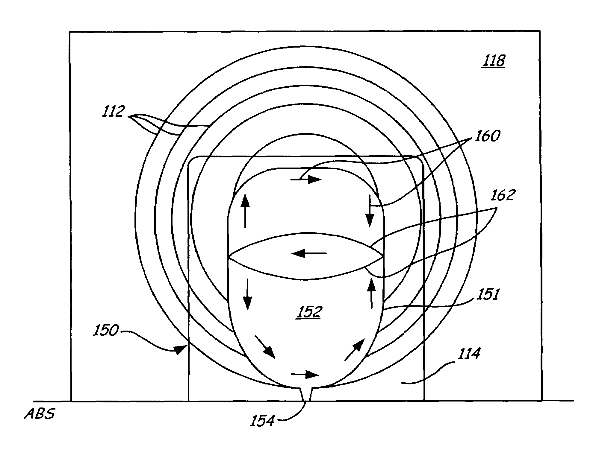
[0023]FIGS. 4, 5, and 6 are top views of a writer portion including a planar rounded top pole according to the present invention. FIG. 4 is a top view of writer portion 150, including rounded top pole 151 according to the present invention. Rounded top pole 151 is located in the same position as top pole 108 in magnetic read / write head 100 of FIG. 1. Top pole 151 includes pole body 152 and pole tip 154. Pole body 152 typically has a generally elliptical shape. Writer portion 150 also preferably includes a yoke (like yoke 109 in FIG. 1) which matches the shape of pole body 152. Also shown are conductive coils 112, shared pole / top shield 114, and bottom shield 118 (to show the relationship of rounded top pole 151 to the components within magnetic read / write head 100 in FIG. 1).
[0024]Top pole 151 is elongated along an axis perpendicular to the air bearing surface, and thus has shape anisotropy perpendicular to the air bearing surface. Top pole 151 is typically composed of a high magnet...
second embodiment
[0026]FIG. 5 is a top view of writer portion 170, including rounded top pole 171 according to the present invention. Rounded top pole 171 is located in the same position as top pole 108 in magnetic read / write head 100 of FIG. 1. Top pole 171 includes pole body 172 and pole tip 174. Writer portion 170 also preferably includes a yoke (like yoke 109 in FIG. 1) which matches the shape of pole body 172. Also shown are conductive coils 112, shared pole / top shield 114, and bottom shield 118 (to show the relationship of rounded top pole 171 to the components within magnetic read / write head 100 in FIG. 1).
[0027]Top pole 171 is elongated along an axis parallel to the air bearing surface, and thus has shape anisotropy parallel to the air bearing surface. Top pole 171 is typically composed of a high magnetic moment material with low coercivity and magnetostriction, such as Ni45Fe55, CoFe, CoNiFe and FeTaN. In top pole 171, magnetization gradually changes its direction when under the influence o...
third embodiment
[0029]FIG. 6 is a top view of writer portion 190, including rounded top pole 191 according to the present invention. Rounded top pole 191 is located in the same position as top pole 108 in magnetic read / write head 100 of FIG. 1. Top pole 191 includes pole body 192 and pole tip 194. Writer portion 190 also preferably includes yoke 196, which has a larger surface area than top pole 191. Also shown are conductive coils 112, shared pole / top shield 114, and bottom shield 118 (to show the relationship of rounded top pole 191 to the components within magnetic read / write head 100 in FIG. 1).
[0030]Top pole 191 has a substantially circular shape, and thus does not have shape anisotropy either parallel or perpendicular to the air bearing surface. Top pole 191 is typically composed of a high magnetic moment material with low coercivity and magnetostriction, and high permeability and electrical resistivity, such as Ni45Fe55, CoFe, CoNiFe and FeTaN. In top pole 191, magnetization gradually change...
PUM
 Abstract
Description
Claims
Application Information