Multicarrier demodulation method and apparatus, and multicarrier modulation method and apparatus

a multi-carrier and modulation method technology, applied in the field of multi-carrier demodulation methods and apparatuses, can solve the problems of lowering communication efficiency and increasing error rates, and achieve the effect of increasing demodulation speed and facilitating the acquisition of linear computations

Inactive Publication Date: 2007-11-20
TOYOTA CENT RES & DEV LAB INC
View PDF9 Cites 14 Cited by
  • Summary
  • Abstract
  • Description
  • Claims
  • Application Information

AI Technical Summary

Benefits of technology

[0038]In particular, the multicarrier demodulation method and apparatus according to the first through fourth features are effective when used to receive a signal modulated by use of inverse discrete Fourier transform, such as OFDM-type signals. This is because signals modulated by use of inverse discrete Fourier transform, such as OFDM-type modulated signals, are typical in terms of design method. That is, it is possible to easily obtain a matrix (linear computation) for demodulation from M samples of a complex signal on the basis of the carrier numbers; i.e., positions on the frequency axis, of subcarriers which are not nullcarriers and the sampling numbers; i.e., positions on the time axis, of M points use...

Problems solved by technology

However, when a delayed wave having an excess delay longer than the guard interval arrives under the influence of multipaths, the error rate increases greatly.
In such a cas...

Method used


Image

  • Multicarrier demodulation method and apparatus, and multicarrier modulation method and apparatus
  • Multicarrier demodulation method and apparatus, and multicarrier modulation method and apparatus
  • Multicarrier demodulation method and apparatus, and multicarrier modulation method and apparatus

Examples


first embodiment

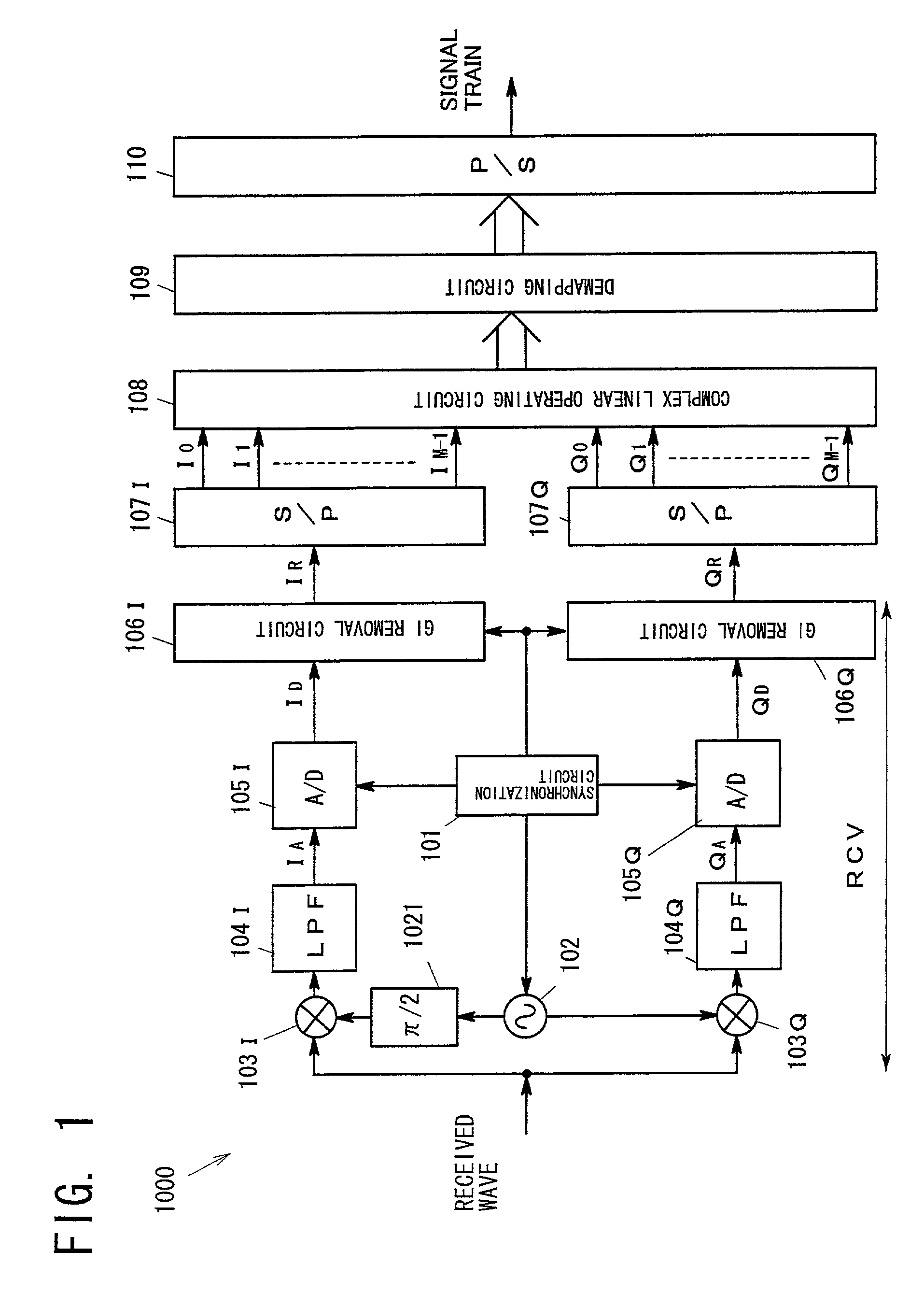
[0097]FIG. 1 is a block diagram showing the configuration of a multicarrier demodulation apparatus 1000 according to a first embodiment of the present invention. The multicarrier demodulation apparatus 1000 corresponds to embodiments of the first to fourth features of the present invention. The multicarrier demodulation apparatus 1000 of the present embodiment receives an OFDM modulated signal which has a guard interval and consists of N subcarriers, including L effective carriers, and performs analog quadrature detection for the signal.

[0098]The multicarrier demodulation apparatus 1000 of FIG. 1 includes a synchronization circuit 101; an oscillation circuit 102; a phase shifter 1021; multipliers 103I and 103Q; LPFs 104I and 104Q; A / D converters 105I and 105Q; GI removal circuits 106I and 106Q; S / P converters 107I and 107Q; a complex linear operating circuit 108; a demapping circuit 109; and a P / S converter 110. Among these circuits, a part indicated as RCV serves as a sampling unit...

second embodiment

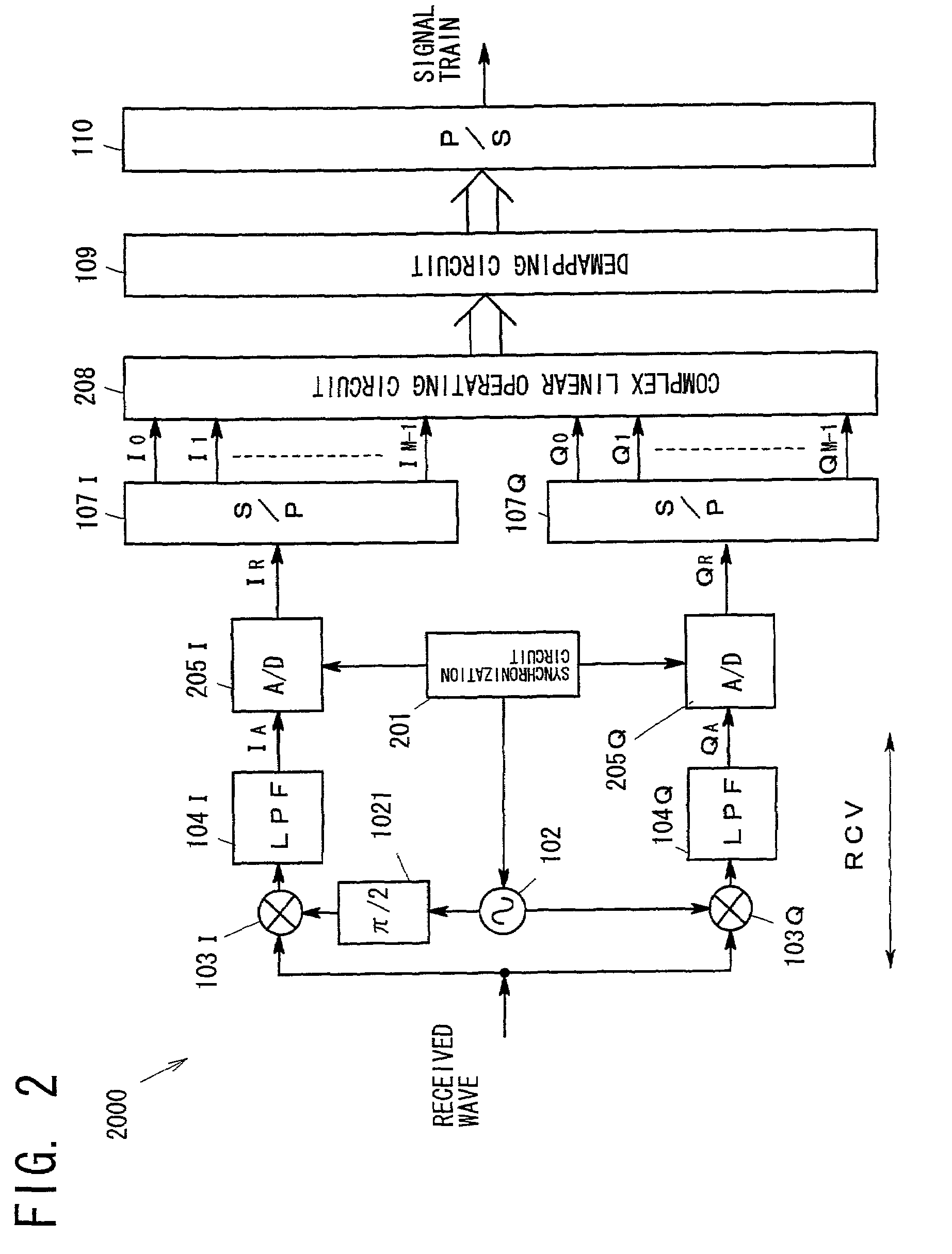
[0104]FIG. 2 is a block diagram showing the configuration of a multicarrier demodulation apparatus 2000 according to a second embodiment of the present invention. The multicarrier demodulation apparatus 2000 corresponds to an embodiment regarding a modification the inventions of the second and fourth features of the present invention.

[0105]Among the constituent elements of the multicarrier demodulation apparatus 2000 of FIG. 2, those which perform the same operations as those performed in the multicarrier demodulation apparatus 1000 of FIG. 1 (excepting operation frequency and operation timing) are denoted by the same reference numerals. The multicarrier demodulation apparatus 2000 of FIG. 2 includes a synchronization circuit 201; an oscillation circuit 102; a phase shifter 1021; multipliers 103I and 103Q; LPFs 104I and 104Q; A / D converters 205I and 205Q; S / P converters 107I and 107Q; a complex linear operating circuit 208; a demapping circuit 109; and a P / S converter 110. Among the...

third embodiment

[0110]FIG. 3 is a block diagram showing the configuration of a multicarrier demodulation apparatus 3000 according to a third embodiment of the present invention. The multicarrier demodulation apparatus 3000 corresponds to another modification of the inventions of the second and fourth features. The multicarrier demodulation apparatus 3000 of the present embodiment also receives an OFDM modulated signal which has a guard interval and consists of N subcarriers, including L effective carriers, and performs analog quadrature detection for the signal.

[0111]Among the constituent elements of the multicarrier demodulation apparatus 3000 of FIG. 3, those which perform the same operations as those performed in the multicarrier demodulation apparatus 1000 of FIG. 1 (excepting operation frequency and operation timing) are denoted by the same reference numerals. The multicarrier demodulation apparatus 3000 of FIG. 3 includes a synchronization circuit 101; an oscillation circuit 102; a phase shif...


PUM


Abstract

A method and apparatus for receiving a modulated signal which consists of N subcarriers containing N-L (L<N) nullcarriers and in which an effective symbol has a length T, and a frequency interval between two adjacent subcarriers of the N subcarriers is 1/T. The method includes estimating an excess delay of a delayed wave, and deciding a part of the symbol regarded as a to-be-used symbol, based on the estimated excess delay, where a length of the decided part is TM/N (M<N) within the effective symbol length T which is decided so as not to contain a part of the symbol suffering from a waveform distortion caused by the delayed wave; and decomposing a complex digital signal which is quadrature-detected at sampling intervals T/N into L subcarriers by use of M samples of the signal within the to-be-used symbol part by means of a matched filter.

Description

[0001]This is a patent application based on Japanese patent application Nos. 2001-204131, 2001-298078, and 2001-299050, which were filed on Jul. 4, 2001, Sep. 27, 2001, and Sep. 28, 2001, respectively, and are incorporated herein by reference.BACKGROUND OF THE INVENTION[0002]1. Field of the Invention[0003]The present invention relates to a demodulation method and apparatus for a multicarrier transmission scheme in which a plurality of subcarriers are modulated individually and the thus-obtained plurality of modulated signals are transmitted over a single symbol duration T. The present invention is particularly effective for a demodulation apparatus which receives a signal modulated in accordance with, for example, orthogonal frequency division multiplexing (OFDM).[0004]The present invention relates further to a multicarrier demodulation method and apparatus. The present invention is particularly effective for reception of OFDM signals at locations where delayed waves exert considera...

Claims


Application Information

Patent Timeline
IPC IPC(8): H04J1/00H04L27/06H04L27/26
CPCH04L27/265H04L27/2628
Inventor SUZUKI, NORIYOSHI
Owner TOYOTA CENT RES & DEV LAB INC
Why Eureka
Try Eureka