Radiographic inspection apparatus and radiographic inspection method

a radiographic inspection and inspection apparatus technology, applied in material analysis using wave/particle radiation, instruments, nuclear engineering, etc., can solve the problems of inability to accurately locate, inability to accurately detect defects, and difficulty in extracting, etc., to achieve the effect of short tim

Inactive Publication Date: 2007-11-20
PANASONIC CORP
View PDF2 Cites 8 Cited by
  • Summary
  • Abstract
  • Description
  • Claims
  • Application Information

AI Technical Summary

Benefits of technology

[0007]An object of the present invention is to provide a radiographic inspection apparatus and a radiographic inspection method so that even a long defect such as a crack intersecting a tomographic plane at right angles can be easily extracted with radiation and a test can be conducted in a short time.
[0014]According to the radiological inspection apparatus and the radiological inspection method, an inspected object is rotated or swung every predetermined degrees of angle, a plurality of tomograms are created using data on penetrated radiations such as an X-ray, a gamma ray, or a neutron ray on each moving position, projected images are created based on the tomograms in a plurality of directions, such as in three directions intersecting at right angles, and a defect is detected based on the projected images. Thus, based on the plurality of projected images, even a long defect such as a crack can be easily and positively detected in any direction.

Problems solved by technology

Thus a defect cannot be correctly located, a blind spot appears in some three-dimensional shapes of the circuit forming device, or inspections are difficult in some regions, so that accurate detection of a defect cannot be expected.
However, in the conventional device for inspecting a defective foreign matter, a long defect such as a crack intersecting a tomographic plane at right angles is reduced in size on the display and thus becomes hard to extract, and processing on a large number of tomographic planes results in a longer inspection time.

Method used


Image

  • Radiographic inspection apparatus and radiographic inspection method
  • Radiographic inspection apparatus and radiographic inspection method
  • Radiographic inspection apparatus and radiographic inspection method

Examples


Embodiment Construction

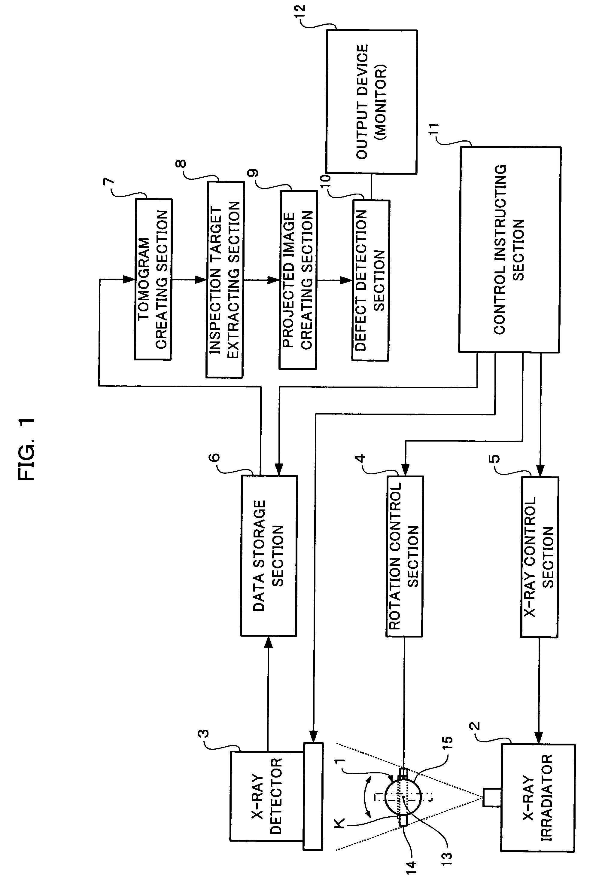
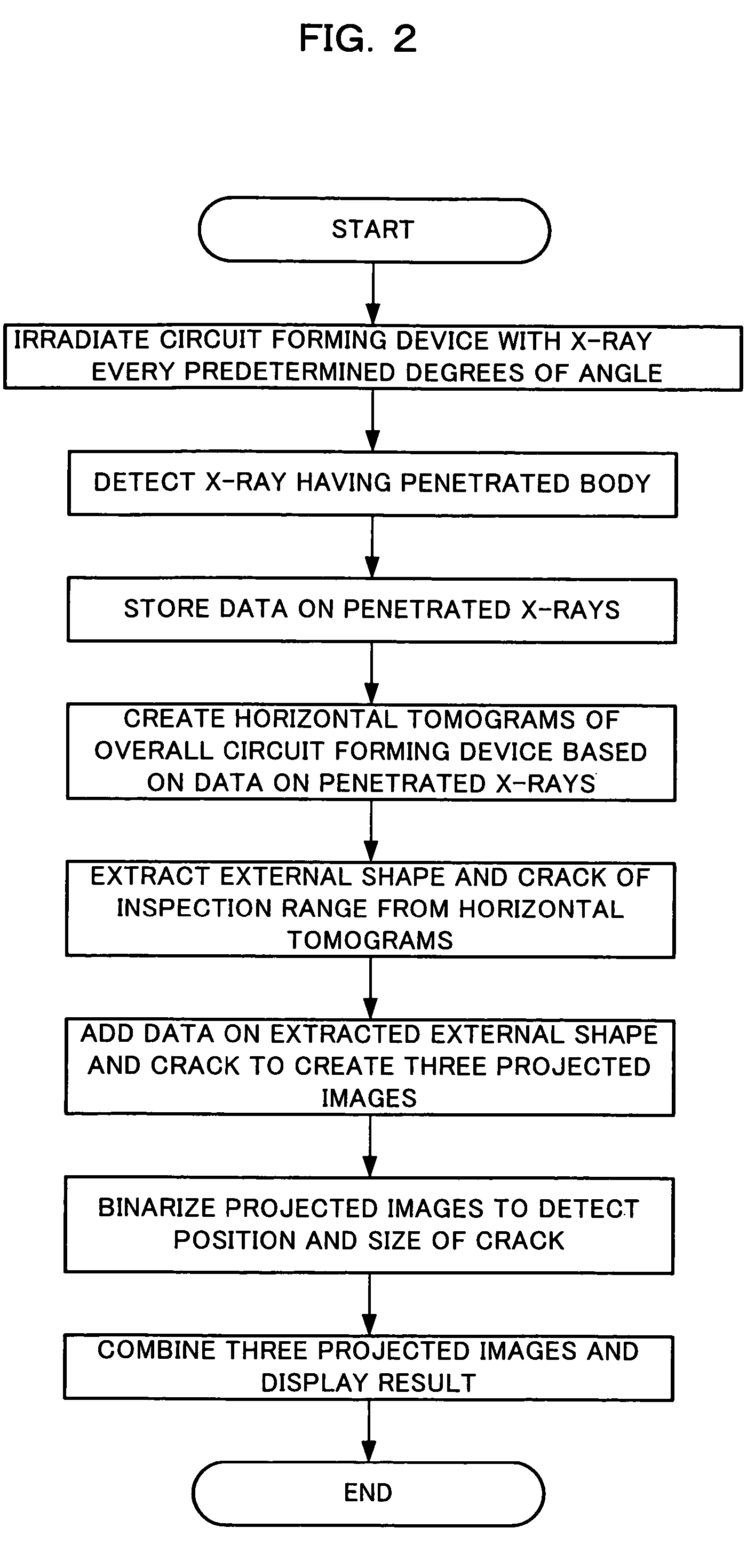
[0026]The following will describe a radiographic inspection apparatus and a radiographic inspection method according to preferable embodiments of the present invention with reference to the accompanying drawings.

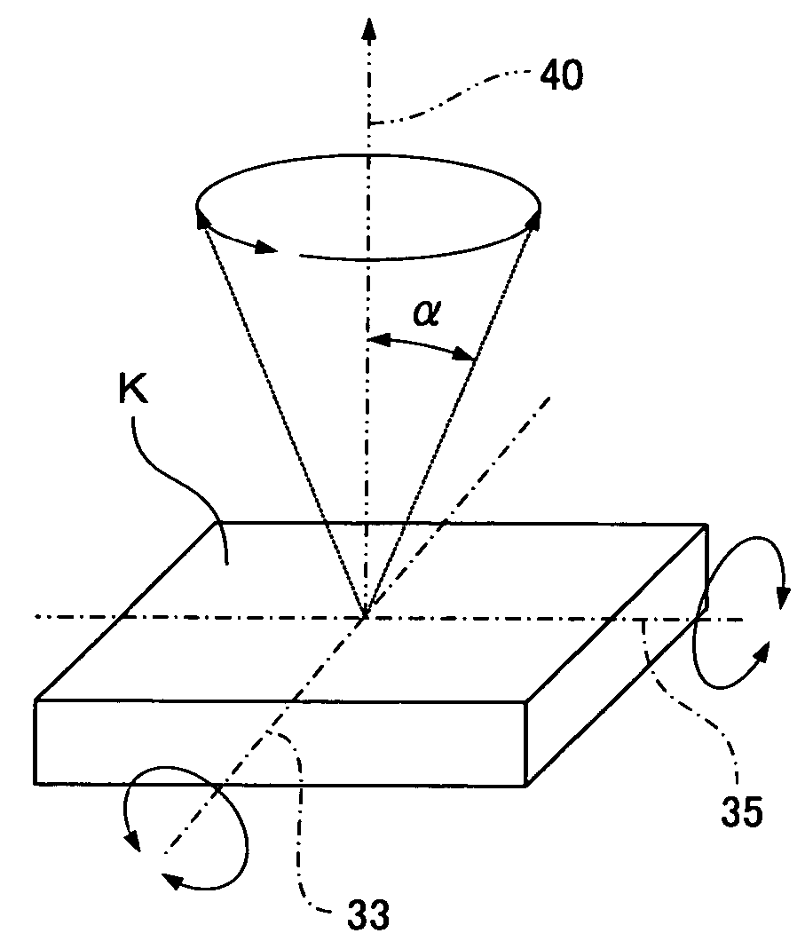
[0027]In the present invention, an inspection is performed using transparent images by radiation. In the specific embodiment, X-rays are used as the radiation.

[0028]In the present embodiment, an inspected object is a circuit forming device. To be specific, the inspected object is a printed board or an electronic component, or the combined or joined printed board and the electronic component. The printed board is applied to a single-sided substrate of paper phenol, a glass epoxy substrate with multiple layers, a film substrate, a substrate including an electronic component, and resin on which a circuit pattern is formed.

[0029]First, an X-ray inspection apparatus will be specifically described below as the radiographic inspection apparatus.

[0030]The X-ray inspection apparatus ...


PUM

PropertyMeasurementUnit
degrees of angleaaaaaaaaaa
focal diameteraaaaaaaaaa

Abstract

A radiographic inspection method of irradiating a circuit forming device with X-rays to inspect the inside of the device. The method includes an X-ray irradiation step of irradiating the circuit forming device with X-rays, an X-ray detection step of detecting X-rays having penetrated the circuit forming device which is rotated every predetermined degrees of angle about an axis intersecting the irradiation direction of X-rays at right angles, a tomogram creating step of creating a plurality of tomograms based on data on penetrated X-rays detected in the X-ray detection step, a projected image creating step of creating projected images in three axial directions intersecting at right angles based on the plurality of tomograms created in the tomogram creating step, and a defect detecting step of detecting a defect such as a crack of the circuit forming device based on the projected images created in the projected image creating step.

Description

FIELD OF THE INVENTION[0001]The present invention relates to a radiographic inspection apparatus and a radiographic inspection method for inspecting a joint state inside a component mounted on a circuit forming device, to be specific a printed board, and a component packaged with resin or metal, or a joint state of a component mounted inside a printed board.BACKGROUND OF THE INVENTION[0002]Conventionally, methods for detecting a defect in a circuit forming device such as a printed board with radiation or X-rays for example, include a method of detection from an image obtained by two-dimensional image processing on an X-ray transparent image in one direction of a circuit forming device, or a method of detection from an image obtained by two-dimensional image processing performed separately on X-ray transparent images in two directions and three directions.[0003]In such detection methods, however, the inside of a circuit forming device can be viewed only in a two-dimensional manner. T...

Claims


Application Information

Patent Timeline
Patent Type & Authority Patents(United States)
IPC IPC(8): G01N23/083
CPCG01N23/046G01N2223/419
Inventor YOSHINO, SHINJI
Owner PANASONIC CORP
Why Eureka
Try Eureka