
Heater for optical gas sensor

a gas sensor and heater technology, applied in the direction of optical radiation measurement, instruments, specific gravity measurement, etc., can solve the problems of not being substantially transparent to the relevant wavelength, temperature-conducting elements may or may not be, etc., to achieve accurate determination of the amount of analyzed material, facilitate accurate measurement, and high transmissivity

Inactive Publication Date: 2007-11-27
RIC INVESTMENTS LLC
View PDF36 Cites 8 Cited by
  • Summary
  • Abstract
  • Description
  • Claims
  • Application Information

AI Technical Summary

Benefits of technology

This solution enables precise temperature control and monitoring of the optical window, reducing condensation and ensuring accurate gas measurements by directly heating the window without compromising the optical pathway.

Problems solved by technology

However, the temperature-conducting element need not be positioned along an optical path of the one or more wavelengths of electromagnetic radiation and, thus, the temperature-conducting element may or may not be substantially transparent to the relevant wavelengths.

Method used


Image

  • Heater for optical gas sensor
  • Heater for optical gas sensor
  • Heater for optical gas sensor

Examples


Embodiment Construction

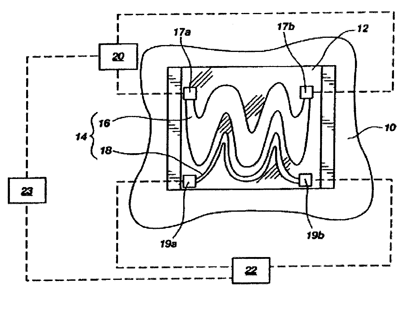
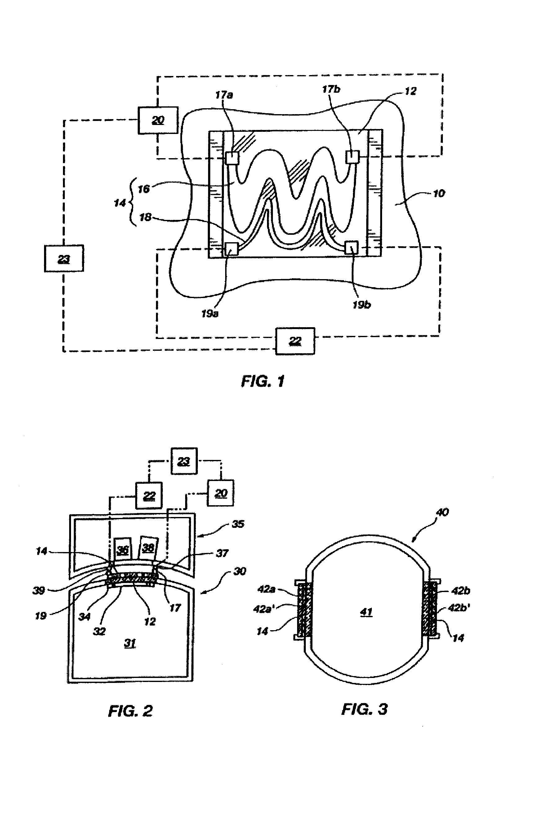
[0043]With reference to FIG. 1, a window 12 of an optical gas sensor 10 is illustrated. A heater 14, which includes a heating element 16, is positioned over a portion of window 12, including over an optical path therethrough, which, in FIG. 1, is transverse to the plane of the page. Heater 14 also includes a temperature-conducting element 18 that extends over a portion of window 12. It will be understood by those of ordinary skill in the relevant art that heating element 16 may be utilized with or without temperature-conducting element 18.

[0044]Heating element 16 may be formed from a substantially transparent conductive material, such as a conductive metal oxide, e.g., tin oxide, indium tin oxide (ITO), antimony tin oxide (ATO), zinc oxide, indium zinc oxide (IZO), etc., cadmium sulfide, zinc oxyfluoride, platinum wire, or the like. Heating element 16 may have a resistance and a thickness that may be controlled as known to those of skill in the relevant art such that the heating ele...


PUM

PropertyMeasurementUnit
diameteraaaaaaaaaa
thicknessaaaaaaaaaa
optical pathaaaaaaaaaa

Abstract

A heater for a window of an optical gas sensor is provided. The heater may be positioned over a portion of the window or may form at least a portion of the window. Alternatively, the heater may be separate from the optical gas sensor and positionable over the window either in contact therewith or in close proximity thereto. In one embodiment, the heater is substantially transparent to the relevant wavelengths of electromagnetic radiation that are used in optical monitoring of respiratory gases, anesthetic agents, or the like. Alternatively, the heater may be configured so as to provide a substantially unobstructed optical pathway through the window. Optical gas sensors and complementary transducers that include the heater are also disclosed.

Description

CROSS-REFERENCE TO RELATED APPLICATION[0001]This application is a Continuation-In-Part (CIP) under 35 U.S.C. § 120 from U.S. patent application Ser. No. 10 / 160,566, filed May 31, 2002, and also claims the benefit under the provisions of 35 U.S.C. § 119(e) from U.S. Provisional application No. 60 / 294,831, filed on May 31, 2001, the contents of each of which are incorporated herein by reference.BACKGROUND OF THE INVENTION[0002]1. Field of the Invention[0003]The present invention relates generally to apparatus for delivering energy to optical windows of diagnostic apparatus and, more specifically, to apparatus that heat optical windows of gas analysis apparatus. In particular, the present invention relates to heaters for use on optical windows of respiratory gas analysis apparatus that provide a substantially unobstructed optical pathway through such optical windows.[0004]2. Description of the Related Art[0005]Various types of sensors that are configured to communicate with the airway ...

Claims


Application Information

Patent Timeline
Patent Type & Authority Patents(United States)
IPC IPC(8): H05B3/00H05B3/84A61B5/083G01N21/03G01N21/35
CPCA61B5/083H05B3/84G01N21/3504G01N21/0332
Inventor DAVIS, RAYMOND G.
Owner RIC INVESTMENTS LLC
Learn More