

Angle position detection apparatus
a technology of angle position and detection apparatus, which is applied in the direction of electronic commutators, dynamo-electric machines, instruments, etc., can solve the problems of increasing the internal space required to install the resolvers in the motor housing, reducing the size and thickness of the direct drive motor, and achieving the effect of reducing the size and thickness of the angle position detection apparatus and high accuracy for angle position detection
- Summary
- Abstract
- Description
- Claims
- Application Information
AI Technical Summary
Benefits of technology
Problems solved by technology
Method used
Image

Examples
first embodiment
[0025]A first embodiment of the present invention will now be described while referring to the accompanying drawings.
[0026]FIG. 3 is a cross-sectional view of a direct drive motor according to this embodiment. As is shown in FIG. 3, in a direct drive motor 10, a rotary shaft 12 rotates freely, supported by a bearing 13 that is fixed to the outer side face of an inner housing 11, which has a hollow cylindrical shape. The rotary shaft 12 is provided as a hollow cylindrical body so that the inner housing 11 can be inserted into it.
[0027]The internal cylindrical wall of the rotary shaft 12 is raised and recessed so as to define, at a gap with the inner housing 11, an inner space 1 within which a unipolar resolver 20 and a multipolar resolver 30 are contained, and an inner space 2 in which a motor 16 is retained. The inner spaces 1 and 2 are separated by the bearing 13, and are located at a specific distance from it to prevent magnetic flux from leaking from the motor 16 and reaching the...
example 3
[0065]This example configuration is a type for detecting the absolute angle position of the rotary shaft 12 within a predetermined angle range. In order to detect the absolute angle position within an angle range of 360 degrees / M, a first resolver is an M-pole resolver and a second resolver is a resolver (e.g., 120 polar teeth) having a high-resolution (M is an integer of two or greater). When the multipolar resolvers are employed in this manner, this configuration is appropriate for an example case wherein the robot arm is pivoted within a predetermined angle range, such as 180 degrees, 120 degrees or 90 degrees. The rotor shape of the first resolver is not especially limited so long as the gap between the resolver rotor and the resolver stator is cyclically changed, and various shapes can be employed. To manufacture the first resolver having two polar teeth, various shapes, such as elliptic shapes, gourd shapes and tooth shapes, can be employed for the resolver rotor.
second embodiment
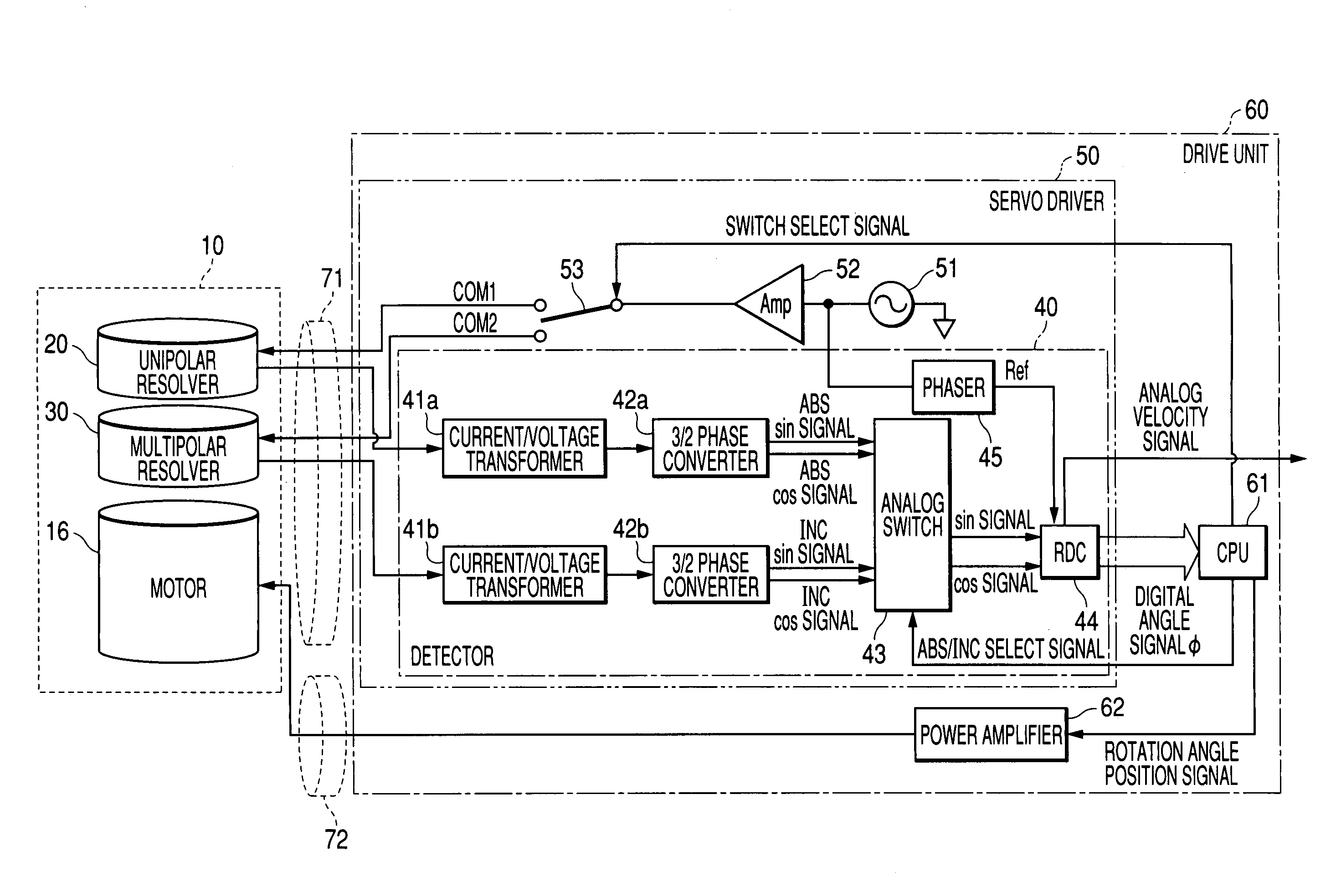
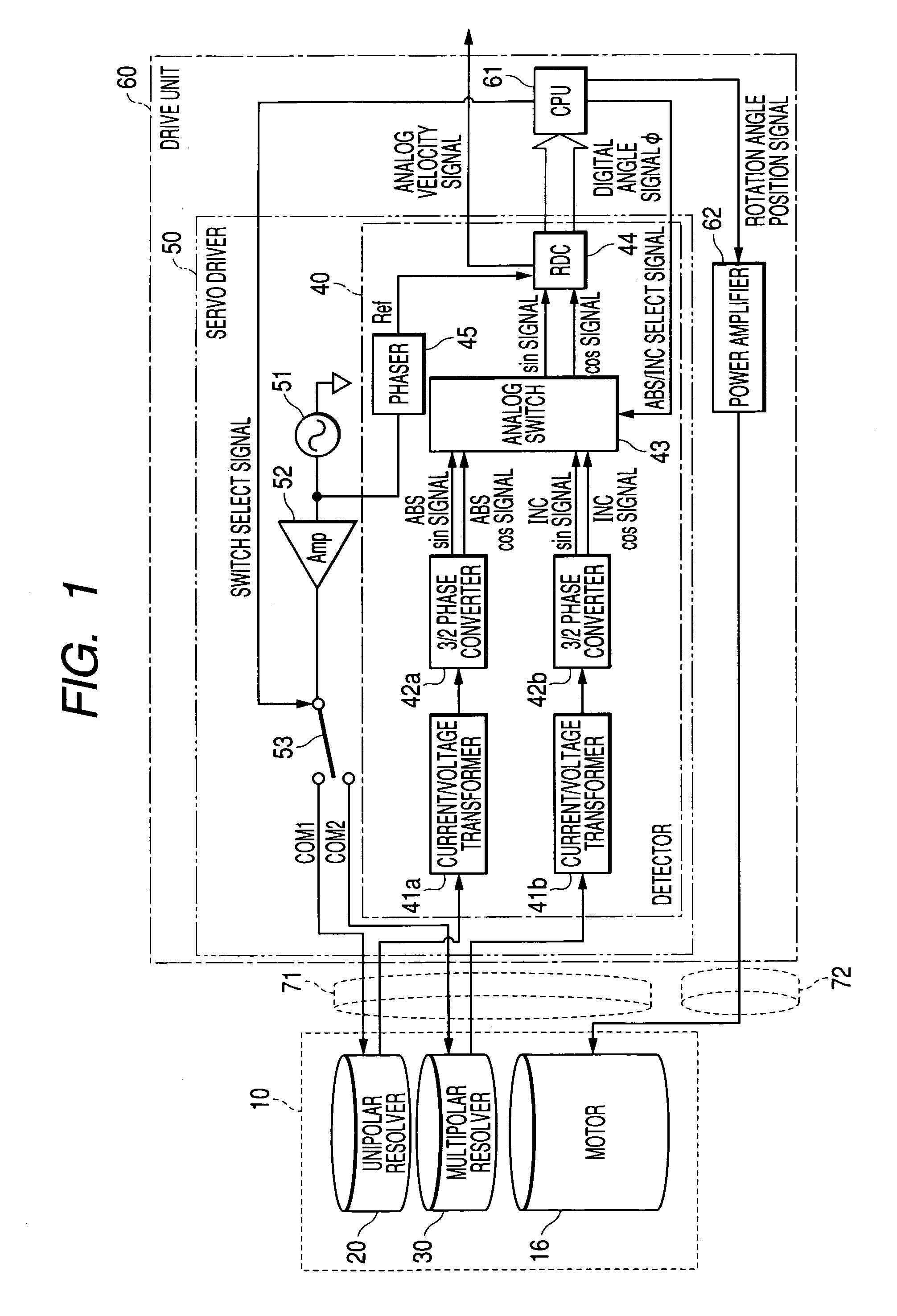
[0066]FIG. 10 is a block diagram showing the configuration of an angle position detection apparatus according to a second embodiment of the present invention. Since the basic configuration is the same as that for the first embodiment, blocks denoted by the same reference numerals as are used in FIG. 1 are assumed to be corresponding components, and for them, no further detailed explanation will be given. When there is a considerable difference in the output current level between a unipolar resolver 20 and a multipolar resolver 30, in order to correctly detect an ABS signal and an INC signal, special components required for signal conversion, e.g., current / voltage transformers 41a and 41b and 3 / 2 phase converters 42a and 42b, as in the first embodiment, must be provided for the individual resolvers 20 and 30, and an analog switch 43 is also required. When the output current level is substantially equal between the unipolar resolver 20 and the multipolar resolver 30, the current / volta...
PUM
 Abstract
Description
Claims
Application Information