Image forming system, image distribution apparatus, and image forming method

Inactive Publication Date: 2007-11-27
CANON KK
View PDF7 Cites 4 Cited by
  • Summary
  • Abstract
  • Description
  • Claims
  • Application Information

AI Technical Summary

Benefits of technology

[0009]It is therefore an object of the present invention to provide an image forming system, an image distribution apparatus, and an image forming method that are capable of making uniform in size printed images, whi

Problems solved by technology

However, the plurality of printers constituting the above conventional printer system differ in amount of heat applied to a transfer sheet during fixing according to print methods such as full-color/black-and-white and print speed, and thus differ in shrinkage amount of a transfer sheet during fixing.
It should be noted that some transfer sheets may not perfectly return to their original sizes even though the transfer sheets absorbs moist

Method used


Image

  • Image forming system, image distribution apparatus, and image forming method
  • Image forming system, image distribution apparatus, and image forming method
  • Image forming system, image distribution apparatus, and image forming method

Examples


first embodiment

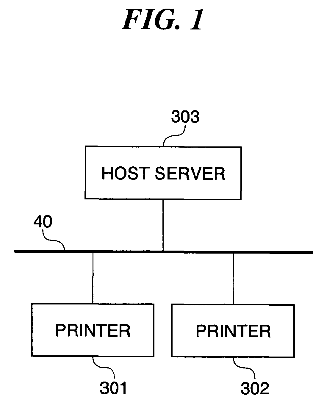
[0054]FIG. 1 is a block diagram showing the arrangement of an image forming system according to the present invention. In FIG. 1, reference numerals 301 and 302 each denote a printer; 40, a network; and 303, a host server that controls the operation of the printers 301 and 302. Although only the two printers 301 and 302 are illustrated, three or more printers may be connected to the network 40. Each printer may perform either black-and-white printing or color printing, and may perform either one-sided printing or double-sided printing.

[0055]The host server 303 communicates with the printers 301 and 302 via the network 40, controls the operation of the printers 301 and 302, distributes images to the printers 301 and 302, and performs image processing.

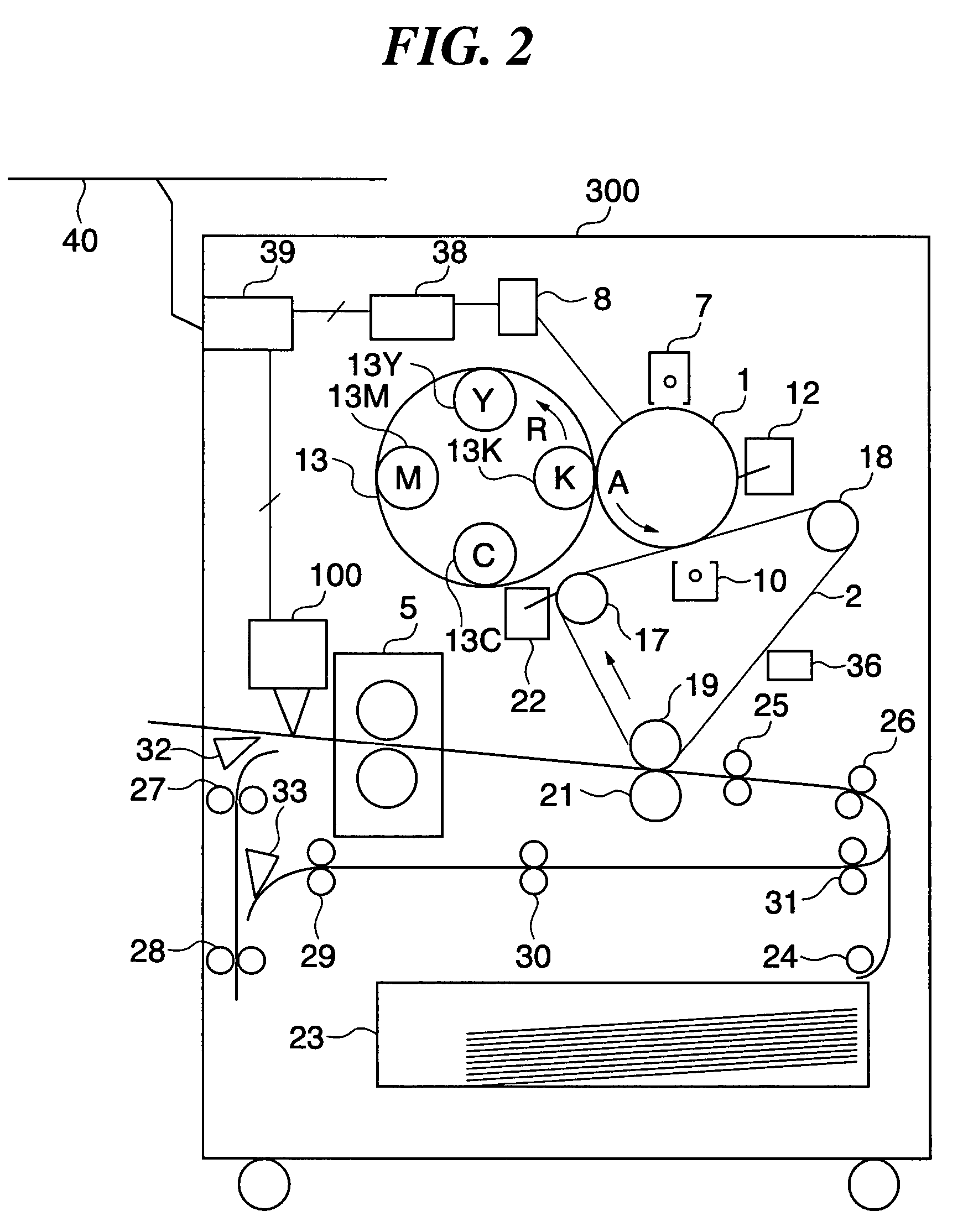
[0056]FIG. 2 is a sectional view schematically showing an example of the construction of one of the printers 301 and 302. Here, an image forming apparatus capable of performing full-color printing and double-sided printing is taken for i...

second embodiment

[0097]A description will now be given of the present invention. The second embodiment is basically identical in construction with the first embodiment, and therefore elements and parts corresponding to those of the first embodiment are designated by identical reference numerals, and duplicate description thereof is omitted.

[0098]FIG. 11 is a block diagram showing the arrangement of an image forming system according to the second embodiment of the present invention. In the second embodiment, one printer is used a master printer 1201, and another printer is used as a slave printer 1202, and they are connected to each other via a cable 1204. Although only one slave printer shown in FIG. 11, there may be a plurality of slave printers. The master printer 1201 and the slave printer 1202 have the same functions as the printers according to the first embodiment, i.e., the function of printing original images and mark images, the function of reading mark images, the function of calculating t...


PUM


Abstract

There is provided an image forming system that is capable of making uniform in size printed images, which should originally be the same in size, between transfer sheets on which the images have been printed by a plurality of printers having different functions and capabilities when enough time has elapsed after fixing. In each of the printers, an image controller or the like forms predetermined marks on a transfer material, and a fixing device thermally fixes of the predetermined marks formed on the transfer material, and a mark detecting device or the like detects the predetermined marks. A host server connected to the printers via a network adjusts the sizes of images to be formed by the respective printers according to the predetermined marks detected by the respective printers, and then transfers the image data to the printers. Each of the printers performs image formation based on the transferred image data.

Description

BACKGROUND OF THE INVENTION[0001]1. Field of the Invention[0002]The present invention relates to an image forming system, an image distribution apparatus, and an image forming method. In particular, the present invention relates to an image forming system comprised of a plurality of image forming apparatuses and an image distributing apparatus that distributes image data to the plurality of image forming apparatuses, an image distribution apparatus to which a plurality of image forming apparatuses are connected and which distributes image data to the plurality of image forming apparatuses, and an image forming method applied to the image forming system.[0003]2. Description of the Related Art[0004]Conventionally, to melt a developing agent (toner) in a thermally fixing process in xerography, a transfer sheet with toner adhered thereto is passed between fixing rollers which are controlled to have a high temperature of about 160 to 200° C. In the case where a normal transfer sheet is u...

Claims


Application Information

Patent Timeline
IPC IPC(8): G06K15/00G03G21/00G03G15/00G06F3/12H04N1/29H04N1/32
CPCH04N1/00015H04N1/00031H04N1/00045H04N1/00082H04N1/32502G06F3/1285H04N1/33369G06F3/1208G06F3/1242H04N1/32529H04N2201/0082H04N2201/33321
Inventor OYUMI, MASASHI
Owner CANON KK
Why Eureka
Try Eureka