Terminals for electrical connector

a technology for electrical connectors and connectors, applied in the direction of multiple conductor connectors, coupling contact members, coupling device connections, etc., can solve the problems of signal disturbance, difficult to match the impedance of chip modules and printed circuit boards, and only on the impedance of socket connectors, etc., to achieve better electrical characteristics

Inactive Publication Date: 2007-12-04
HON HAI PRECISION IND CO LTD
View PDF8 Cites 42 Cited by
  • Summary
  • Abstract
  • Description
  • Claims
  • Application Information

AI Technical Summary

Benefits of technology

[0007]A primary object of a preferred embodiment of the present invention is to provide a terminal having a better electrical characteristic enabling reliable signal transmission circuit between two electrical surfaces.
[0009]Compared with the conventional the socket connector, the terminal of the present invention comprises at least the following merits: during the signal transmitting, the capacitive effect produced by the plate-like members disposed between the first electrical interface and the second electrical interface can adjust the impedance of the terminals, so the match between the terminal and the electrical interface is realized. In addition, the plate-like member may improve the shielding efficacy so that the signal interference between two adjacent terminals during the signal transmission can be prevented.

Problems solved by technology

However, said terminals described in the prior arts at least exist the following flaws: the impedance of the socket connector only relies upon the mechanical features of the base portion, the arm portion and the solder portion, which is difficult to match the impedance of the chip module and the printed circuit board.
Moreover, while the developing trend of the socket connectors is high density and compact type, and the distances between the terminals of become narrower and narrower, which will produce signal disturbance between two adjacent terminals during signal transmission.

Method used


Image

  • Terminals for electrical connector
  • Terminals for electrical connector
  • Terminals for electrical connector

Examples


second embodiment

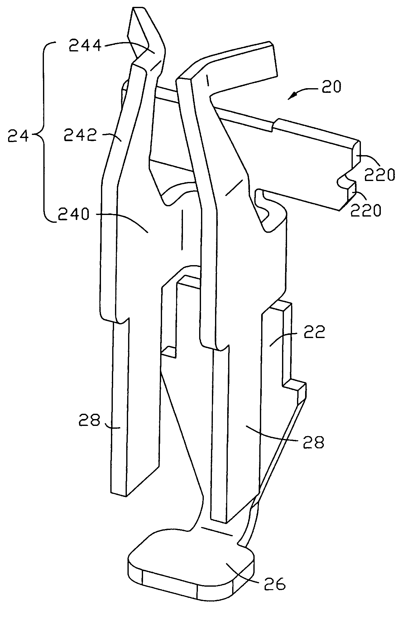
[0024]A terminal 20 in accordance with the invention shown in FIG. 4, comprises a plate-like base portion 222 extending along a vertical direction, an arm portion 24 extending upwardly from two sides of the base portion 22 and bending oppositely with each other, a solder portion 26 extending horizontally from a distal end of the base portion 22. Two sides of the base portion 22 define pairs of barbs 220 adjacent a top end thereof for holding the terminal 20 steadily. The arm portion 24 defines a connection arm 240, an extending arm 242 extending arcuately from an end of the connection arm 240 far away from the base portion 22 oppositely upwardly and inwardly, a contact arm 244 extending horizontally from a top end of the extending arm 242 to the base portion 22. The contact arm 244 defines a smooth curve interface and extends outwardly. Each of the lower ends of the connection arm 240 defines a plate-like member 28, respectively. The plate-like members 28 disposed oppositely extend ...

third embodiment

[0025]Referring to the FIG. 5, a terminal 30 of the invention is described, The terminal 30 defines a plate-like base portion 32 extending uprightly. A plurality of barbs 320 for holding the terminals 32 reliably is disposed on the top end of the base portion's opposite sides. A pair of arm portions 34 is disposed on two opposite sides of the base portion 32 extending uprightly and bent oppositely. Each arm portion 34 comprises a connection arm 340 connecting with a lateral side of the base portion 32, an extending arm 342 extending from an end of the connection 340 arm far away from the base portion 32 bent inwardly and upwardly, a contact arm 344 extending from the top end of the extending arm 342 to the base portion 32 horizontally. The contact arm 344 is provided with a smooth curved interface extending towards the base portion 32 outwardly. A horizontal solder portion 36 is disposed on a lower end of the base portion 32. Each lateral side of the solder portion 36 sides defines ...

fourth embodiment

[0026]FIG. 6 is an isometric view of a terminal 40 of a Each terminal 40 defines a plate-like base portion 42 extending from the upright direction, a pair of arm portions 44 extending from two sides of the base portion 42 and bent oppositely and a solder portion 46 extending horizontally and perpendicularly to a distal end of the base portion 42. A plurality of the barbs 420 is disposed on preferred positions of the two sides of the base portion 42 for holding the terminal 40 steadily. The arm portion 44 comprise a connection arm 440 connecting with the base portion 42, an extending arm 442 extending from an end of the connection 440 arm far away from the base portion 42 bent inwardly and upwardly and a contact arm with smooth curved interface extending outwardly in a direction of the base position 42 and connecting with the extending portion 442. A pair of plate-like members 48 is formed on the sides of solder portion 46 opposite to the base portion 42. The plate-like members 48 i...


PUM


Abstract

A terminals (10) for use in connection of a first electrical interface (50) and a second interface (60), comprises a base portion (12) extending between the first electrical interface and the second electrical interface, a pair of arm portions (14) extending from two lateral sides of the base portion toward the first electrical interface, a solder portion (16) extending outwardly from the base portion (12) towards the second electrical interface, and at least one plate-like member disposed between the arm portion (14) and the solder portion (16) of the terminal (10).

Description

BACKGROUND OF THE INVENTION[0001]1. Field of the Invention[0002]The present invention relates generally to terminals for connecting a first electrical interface to a second interface, such as a chip module to a printed circuit board (PCB), for providing a better circuit connection.[0003]2. Background of the Invention[0004]Integrated circuit (IC) devices, especially pin grid array (PGA) devices, are widely used in a zero insertion force connector or a low insertion force connector for building a signal transmission circuit between leads of a chip module and corresponding welding points of a printed circuit board. Conventional terminal having high contact performance described in U.S. Pat. Nos. 6,319,038 and 6,830,471 comprise a base portion extending uprightly, a pair of arm portions extending upwardly from the two sides of the base portion and bent opposite to each other, a solder portion disposed on a distal of the base portion, respectively. In use, the base portion of the termina...

Claims


Application Information

Patent Timeline
Patent Type & Authority Patents(United States)
IPC IPC(8): H01R11/22
CPCH01R4/02H01R12/714H01R11/05
Inventor LIAO, CHI-NAN
Owner HON HAI PRECISION IND CO LTD
Why Eureka
Try Eureka