Human/machine interface for a machine vision sensor and method for installing and operating the same

Inactive Publication Date: 2007-12-04
COGNEX TECH & INVESTMENT
View PDF17 Cites 156 Cited by
  • Summary
  • Abstract
  • Description
  • Claims
  • Application Information

AI Technical Summary

Benefits of technology

[0016]This invention overcomes the disadvantages of the prior art by providing a human/machine interface (HMI) for use with machine vision systems (MVSs) that provides the machine vision system processing functionality at the sensor end of the system, and uses a communication interface to exchange control, image and analysis information with a standardized, preferably portable HMI device. Significantly, the HMI device can be disconnected from the sensor during runtime of the sensor, and the sensor's internal processing element can carry on machine vision tool activity as configured by the HMI device.
[0017]In an illustrative embodiment, this portable device can be a web-browser equipped computer (handheld, laptop or fixed PC), a Personal Digital Assistant (PDA), or another form of remote computing device that can be configured to include a generic web-browser application or another specialized interface application. The communication interface on the sensor-end of the system is adapted to communicate over a cable interconnect (serial, Ethernet, Universal Serial Bus (USB (Version 1.0/2.0)), or a wireless communication link (for example infrared (IR) or radio frequency (RF)), with a corresponding communication interface in the portable device. The data communicated over the interconnect or link is formatted so that it is read at a data speed and level of resolution (pixel count) that is appropriate to the portable device by use of an image processor at the sensor end. The processor, accordingly includes an application that supports transmission and receipt of data in a desired portable-device compatible format and sp

Problems solved by technology

While the PC (laptop and desktop) is a powerful tool for providing a HMI, the cost of laptop and desktop PCs has not fallen appreciably over the past several years—due, in part, to their large component-count, complexity and continued improvement by manufacturers as a tradeoff against constant unit cost.
Much of this increased computing power may be unnecessary for a standard MVS HMI.
In addition, the weight and size of PCs and their displays has limited by their ergonomics.
In other words, keyboards, mice, hard drives and displays take up space and cannot be overly miniaturized.
There are also hidden costs to operating one or more PCs as HMIs.
The PC's complexity means that it typically requires periodic intervention by costly Information Technology professionals to repair and upgrade operating system, networking and application software.
Conversely, the size, and cost of machine vision sensors has continued to fall over the years, and they have been deployed at an increa

Method used


Image

  • Human/machine interface for a machine vision sensor and method for installing and operating the same
  • Human/machine interface for a machine vision sensor and method for installing and operating the same
  • Human/machine interface for a machine vision sensor and method for installing and operating the same

Examples


Embodiment Construction

[0029]I. System Overview

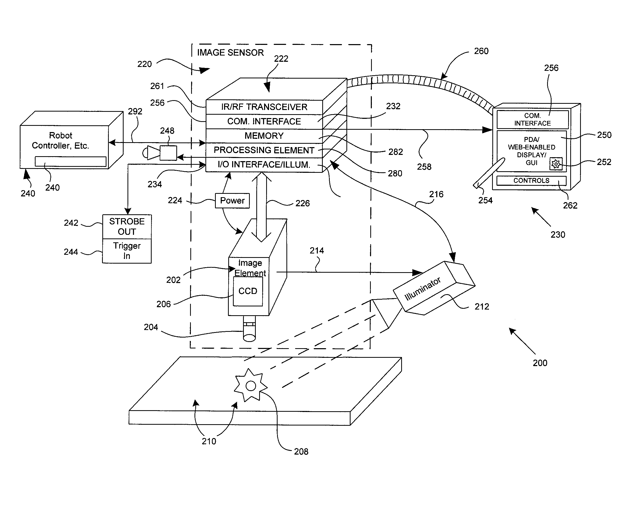
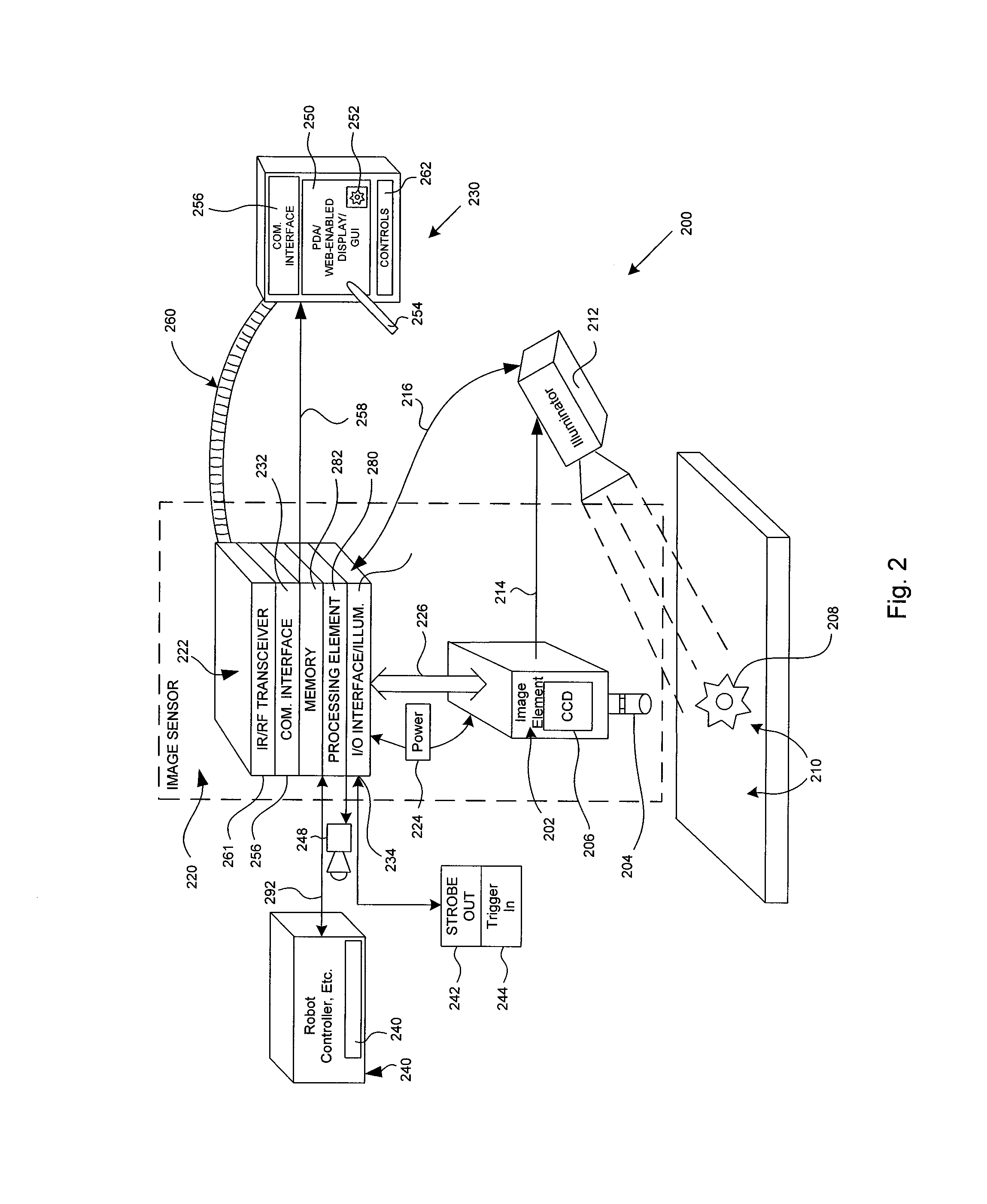
[0030]FIG. 2 shows an illustrative embodiment of a machine vision system (MVS) 200 according to this invention. The MVS includes an image element 202 having a lens 204 with variable zoom and focus / aperture setting, and an electro-optical pickup (CCD) 206 for generating an of image signal of an object (the exemplary gear) 208 within the relevant field of view within the viewing area 210. A framegrabber or similar image capture device can also be included within the image element. An optional illuminator 212 for directing light at the object 208 and viewing area 210 is provided. A variety of types of illuminators (e.g. direct, indirect, backlight) can be employed. Likewise the positioning and number of illuminators is highly variable. Such illuminators can be integral with the image element 202 and powered by it as shown by the direct connection 214. Alternatively, the illuminator can be controlled and / or powered via an I / O interface via the connection 216. Thi...


PUM


Abstract

This invention overcomes the disadvantages of the prior art by providing a human/machine interface (HMI) for use with machine vision systems (MVSs) that provides the machine vision system processing functionality at the sensor end of the system, and uses a communication interface to exchange control, image and analysis information with a standardized, preferably portable device that can be removed from the MVS during runtime. In an illustrative embodiment, this portable device can be a web-browser equipped computer (handheld, laptop or fixed PC) or a Personal Digital Assistant (PDA). The communication interface on the sensor-end of the system is adapted to communicate over a cable or wireless communication link (for example infrared (IR) or radio frequency (RF)), with a corresponding communication interface in the portable device. The data communicated over the interconnect or link is formatted so that it is read at a data speed and level of resolution (pixel count) that is appropriate to the portable device by use of an image processor at the sensor end.

Description

FIELD OF THE INVENTION[0001]This invention relates to machine vision systems, and more particularly to human / machine interfaces for training, controlling and monitoring machine vision system sensors and methods for installing and configuring such interfaces.BACKGROUND OF THE INVENTION[0002]Machine vision systems are used for a growing variety of manufacturing and inspection processes in research and industry. A machine vision system enables a user to monitor subject parts and workpieces, either at stationary locations or on moving lines, and to compare acquired images of the subjects to trained patterns, stored in a memory.[0003]FIG. 1 shows a typical arrangement for a basic machine vision system 100 according to the prior art. An image sensor unit 102 is directed at an object (exemplary gear 104) within the viewing area 108 of the image sensor 102. The sensor includes a lens 110 of appropriate viewing angle, aperture and magnification. These parameters can be varied, either by remo...

Claims


Application Information

Patent Timeline
IPC IPC(8): G06K9/00G06K9/40G06K9/62H04N7/00H04N7/18H04N9/47G06F15/16
CPCG06K9/6253G05B2219/37494G05B2219/37563G06F18/40
Inventor WOLFF, ROBERTSILVER, WILLIAM
Owner COGNEX TECH & INVESTMENT
Why Eureka
Try Eureka