Fuel injection system ensuring operation in event of unusual condition

a fuel injection system and unusual condition technology, applied in the direction of fuel injection apparatus, charge feed system, electric control, etc., can solve the problems of insufficient number of corrections, inability to ensure the stability of engine operation, and inability to ensure engine operation stability

Inactive Publication Date: 2007-12-11
DENSO CORP
View PDF21 Cites 48 Cited by
  • Summary
  • Abstract
  • Description
  • Claims
  • Application Information

AI Technical Summary

Benefits of technology

[0012]It is another object of the invention to provide an improved structure of a fuel injection system designed to ensure the stability of operation of an engine in the event of a problem such as a change in performance or failure in operation of a rail pressure sensor.
[0016]The controller may use the calculated value of the rail pressure to control operations of the fuel injectors for subsequent injections of the fuel into the engine. This eliminates the need for an output of the rail pressure sensor.

Problems solved by technology

If the rail pressure sensor is changed in performance or has failed in operation thereof, it will impinge upon the operation of the engine undesirably.
The number of the corrections is, therefore, not always sufficient for ensuring the stability of operation of the engine.
The system is designed only to correct the offset error of the output of the rail pressure sensor and cannot always assure the stability of operation of the engine if another problem, such as a change in performance or a failure in operation of the rail pressure sensor, has occurred.

Method used


Image

  • Fuel injection system ensuring operation in event of unusual condition
  • Fuel injection system ensuring operation in event of unusual condition
  • Fuel injection system ensuring operation in event of unusual condition

Examples


first embodiment

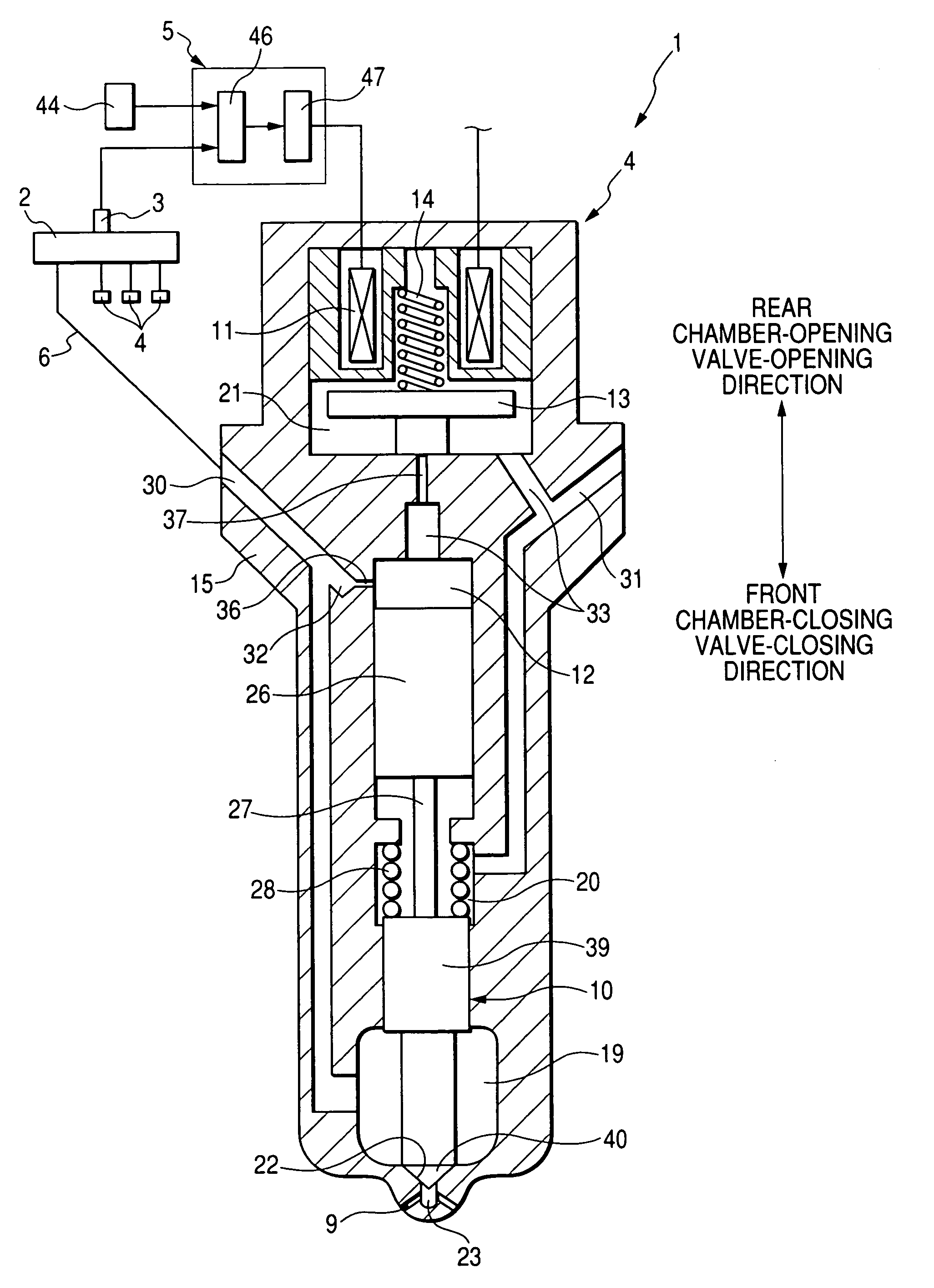
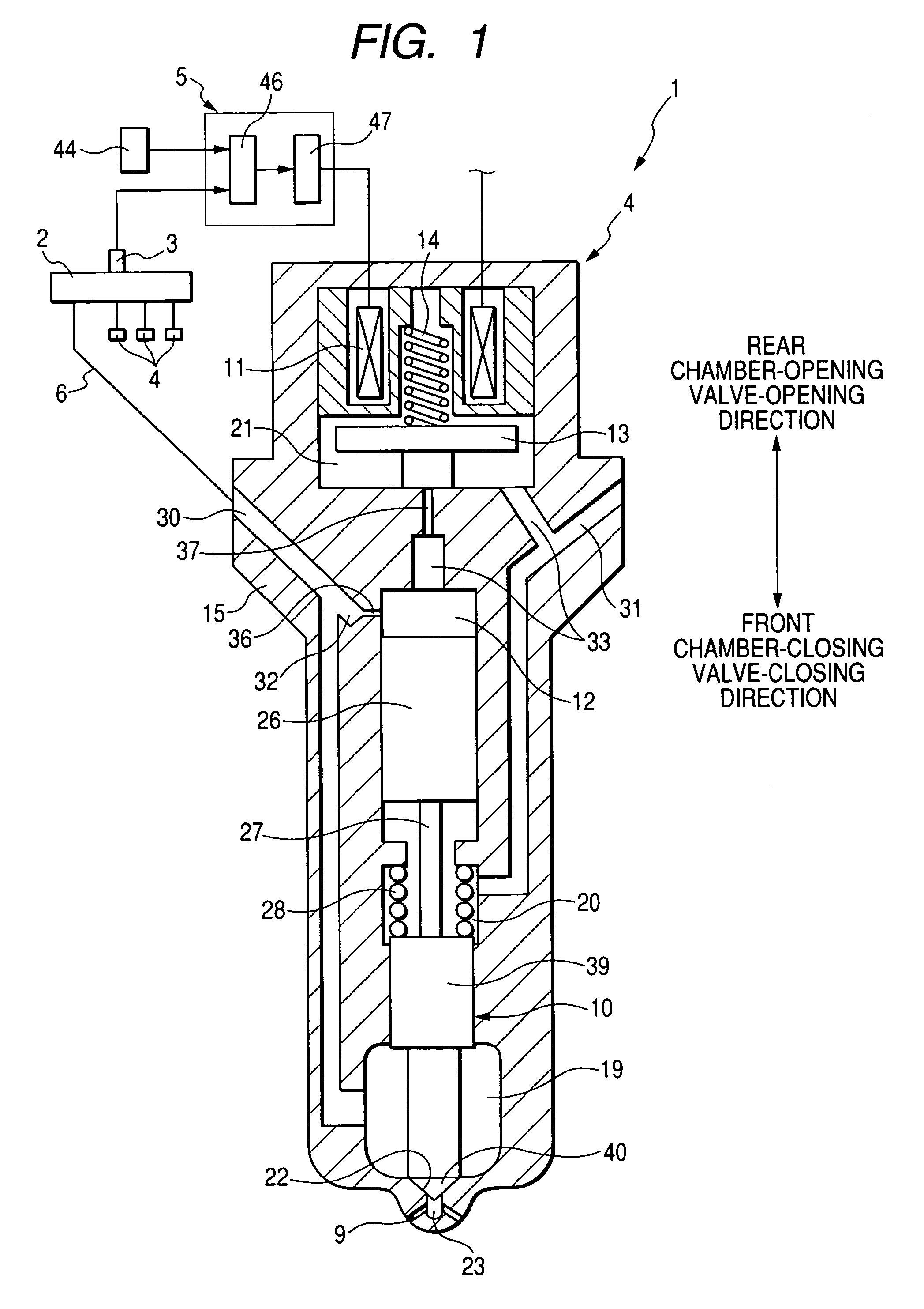
[0033]Referring to the drawings wherein like reference numbers refer to like parts in several views, particularly to FIG. 1, there is shown an automotive fuel injection apparatus 1 according to the invention.

[0034]The fuel injection apparatus 1, as referred to herein, is engineered as a common rail injection apparatus for internal combustion engines such as four-cylinder direct fuel injection diesel engines.

[0035]The fuel injection apparatus 1 includes a common rail 2 in which fuel pressurized and discharged by a fuel pump (not shown) is accumulated, a rail pressure sensor 3, fuel injectors 4, and a controller 5. The rail pressure sensor 3 works to measure the pressure of the fuel within the common rail 2 and output a signal indicative thereof to the controller 5. Each of the fuel injectors 4 connects with the common rail 2 and works to spray fuel into one of cylinders of the engine. The controller 5 works to monitor an output of the rail pressure sensor 3 to control operations of t...

second embodiment

[0075]The fuel injection apparatus 1 will be described below.

[0076]The controller 5 is designed to monitor the operation of the rail pressure sensor 3 to determine whether a fault, such as a wire breakage or disconnection, has occurred in the rail pressure sensor 3 or not, change the maximum values of the greater currents to the fuel injectors 4, in sequence, in the same direction, monitor a resulting change in variation in revolution of the engine, and estimate or calculate the rail pressure below based on the maximum value of the greater current, as applied to one of the injectors 4 upon detection of the change in variation in revolution of the engine, and the physical property of balance among forces acting on the control valve 13 of the one of the injectors 4 upon detection of the change in variation in revolution of the engine, and control the injection of fuel into the engine using the calculated rail pressure.

[0077]The controller a selects one of the cylinders of the engine ...

third embodiment

[0086]The fuel injection apparatus 1 will be described below.

[0087]Each of the injectors 4, as employed in the fuel injection apparatus 1 of this embodiment, includes, as illustrated in FIG. 8, a piezoelectric actuator made of a piezoelectric device 49. When it is required to inject the fuel into one of the cylinders of the engine, the controller 5 applies the voltage to the piezoelectric device 49 of a corresponding one of the injectors 4. The piezoelectric device 49 is responsive to the application of voltage thereto to expand in a lengthwise direction thereof to produce a pressure or force Fpzt(V) (which will also be referred to as a piezo expansion force below) urging the control valve 13 to close the back pressure chamber 12. The magnitude of the piezo expansion force Fpzt(V) is a function of the voltage (V) applied to the piezoelectric device 49.

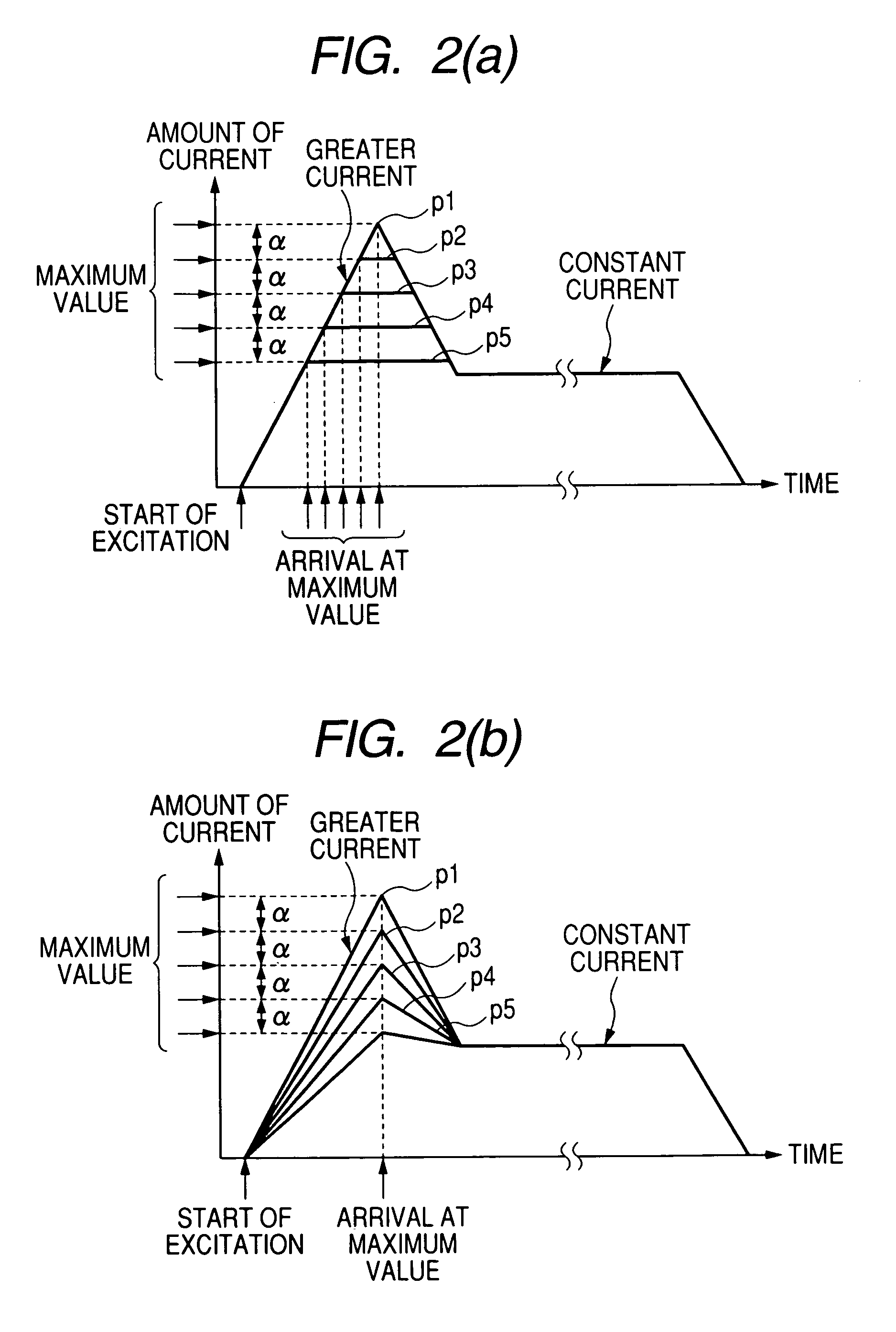
[0088]The controller 5 has a piezoelectric device excitation schedule, like the one of FIG. 2(a) or 2(b), which represents a sequent...


PUM


Abstract

A common rail fuel injection apparatus for an engine is provided which is equipped with a rail pressure sensor working to measure the pressure of fuel in a common rail, fuel injectors, and a controller. When the operation state of the rail pressure sensor monitored to be unusual, the controller changes the value of electricity supplied to an actuator of one of the fuel injectors to induce a change in a preselected operation characteristic of the engine. Upon appearance of such a change, the controller estimates the value of the rail pressure using the changed value of the electricity and a physical property of balance among forces acting on a valve of one of the fuel injectors which has induced the change in operation characteristic of the engine. The estimated value of the rail pressure is used for subsequent injections of the fuel into the engine.

Description

CROSS REFERENCE TO RELATED DOCUMENT[0001]The present application claims the benefit of Japanese Patent Application No. 2005-14670 filed on Jan. 21, 2005, the disclosure of which is incorporated herein by reference.BACKGROUND OF THE INVENTION[0002]1. Technical Field of the Invention[0003]The present invention relates generally to a common rail fuel injection system designed to ensure the stability of operation of an engine in the event of an operating problem.[0004]2. Background Art[0005]There are known accumulator fuel injection systems designed to inject fuel into an internal combustion engine at high pressure through a common rail. Such systems are usually employed in injecting the fuel to direct injection engines such as diesel engines.[0006]Typically, fuel injection systems of the above type include a common rail in which fuel pressurized and discharged by a fuel pump is accumulated under high pressure, a rail pressure sensor working to measure the pressure of the fuel in the co...

Claims


Application Information

Patent Timeline
Patent Type & Authority Patents(United States)
IPC IPC(8): F02M57/02F02M51/00
CPCF02D41/3836F02M63/0225F02M47/027F02D41/1498F02D41/20F02D2200/0604F02D2041/2058
Inventor FUJII, HIROTO
Owner DENSO CORP
Why Eureka
Try Eureka