Method and apparatus for stabilizing a plasma

Inactive Publication Date: 2007-12-11
SURFACE TECH SYST
View PDF19 Cites 17 Cited by
  • Summary
  • Abstract
  • Description
  • Claims
  • Application Information

AI Technical Summary

Benefits of technology

[0015]The matching unit may be driven by a motor. In one embodiment control signals are used to drive the motor and may be modified to track impedance changes rapidly, in order to minimise or eliminate “overshoot” as described in detail below.
[0027]According to a second aspect of the present invention, there is provided a plasma processing apparatus comprising a chamber having a support for a workpiece, means for striking a plasma in the chamber, means for cyclically adjusting processing parameters between a first step and a second step, and means for stabilizing the plasma during the transition between the first and second steps.

Problems solved by technology

The request for sudden changes in, for example, the gas pressure or discharge power between the states may lead to plasma instability or even lead to the plasma extinguishing.
During the change from one step to another step, plasma instability or extinguishing of the plasma may result.

Method used


Image

  • Method and apparatus for stabilizing a plasma
  • Method and apparatus for stabilizing a plasma
  • Method and apparatus for stabilizing a plasma

Examples


Embodiment Construction

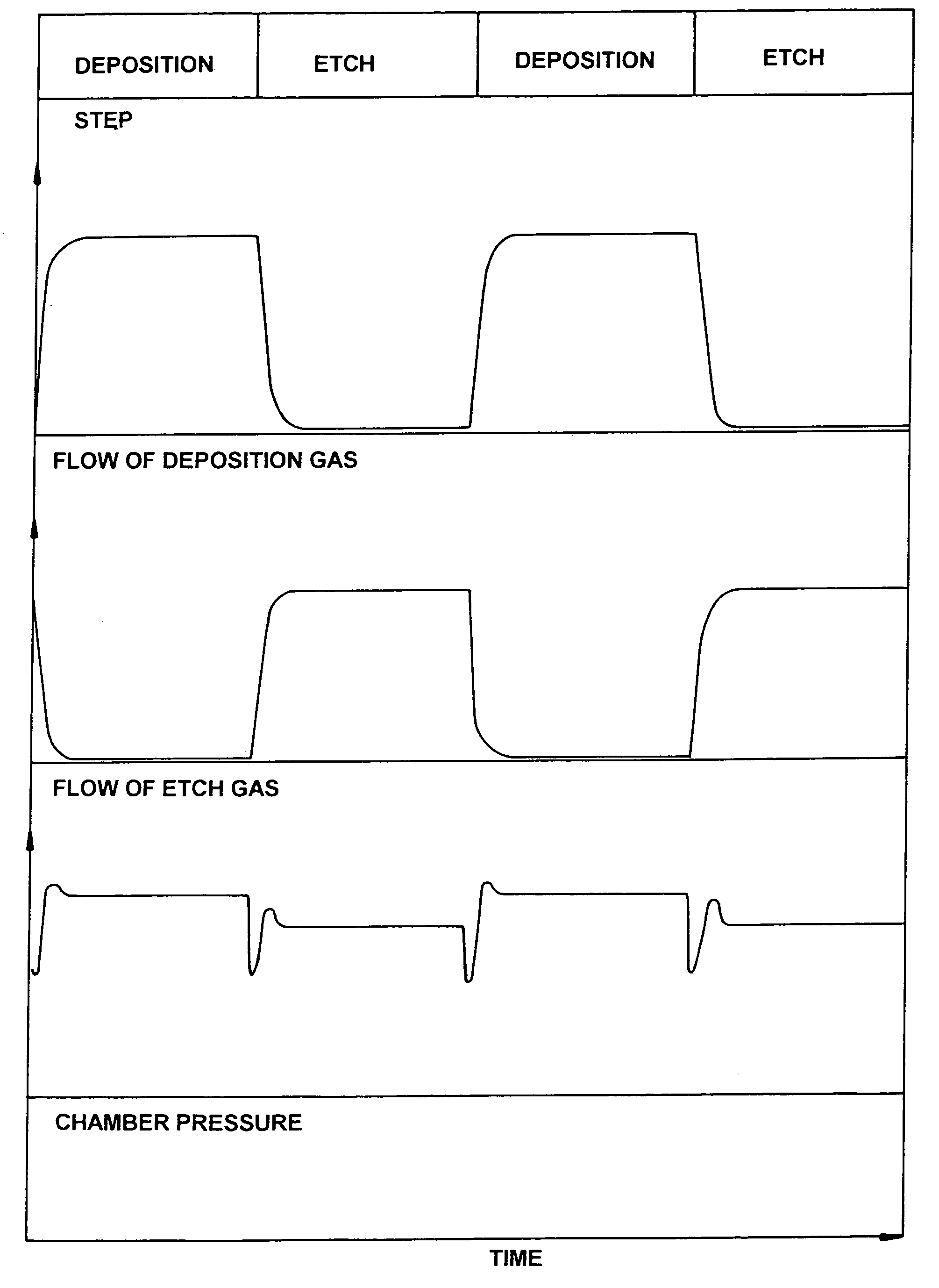
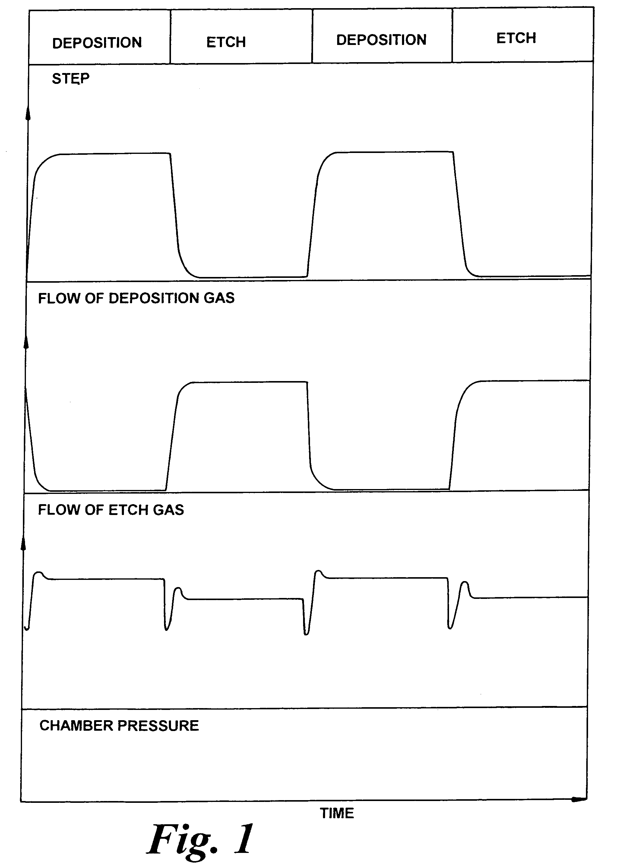
[0038]Referring to FIG. 1, the flow of deposition gas and etch gas and the chamber pressure is shown during a typical etch / deposition cyclic process. In changing from the etch step to the deposition step or vice versa, the process gas is switched. That is the mass flow controller, or alternative means (such as an actuating device which diverts the gas flow around the process chamber), controlling the first gas, is switched off, and the mass flow controller controlling the second gas is switched on. The switching on or off of each process gas may be on a reasonably short time scale, or one or other action may be more gradual, over a longer time scale. There may or may not be a period during which both types of process gas are being fed to the process chamber simultaneously, as the flow of one is being reduced and the flow of the other is being increased. The required flow levels of the two gases may be quite different and also the pressures required in the process chamber during each...


PUM

PropertyMeasurementUnit
Timeaaaaaaaaaa
Pressureaaaaaaaaaa
Poweraaaaaaaaaa

Abstract

A workpiece is processed in a chamber by striking a plasma in the chamber, treating the workpiece by cyclically adjusting the processing parameters between at least a first step having a first set of processing parameters and a second step having a second set of process parameters, wherein the plasma is stabilized during the transition between the first and second steps. These steps may comprise cyclic etch and deposition steps. One possibility for stabilizing the plasma is by matching the impedance of the plasma to the impedance of the power supply which provides energy to the plasma, by means of a matching unit which can be controlled in a variety of ways depending upon the step type or time during the step. Another possibility is to prevent or reduce substantially variation in the pressure in the chamber between the first and second steps.

Description

BACKGROUND OF THE INVENTION[0001]This invention relates to a method and apparatus for processing a workpiece in which a plasma struck in the chamber is stabilized during the transition between steps, particularly, although not exclusively, steps in a cyclic process in the treatment of the workpiece.[0002]The plasma processing of a wafer or other workpiece may require certain plasma parameters to change between two or more states cyclically. The request for sudden changes in, for example, the gas pressure or discharge power between the states may lead to plasma instability or even lead to the plasma extinguishing.[0003]A particular method to achieve highly anisotropic etches for high aspect ratio trenches is to use a switched process in which an etch step is alternated with a deposition step. Such a method is disclosed in WO-A-94 / 14187, EP-A-0822582 and EP-A-0822584. In the case of deep trench silicon etching, a passivating layer may be deposited on all surfaces of the wafer (includi...

Claims


Application Information

Patent Timeline
IPC IPC(8): B44C1/22B01J19/08H05H1/46B81C1/00C23C16/507C23C16/52H01J37/32H01L21/205H01L21/302H01L21/3065
CPCH01J37/321H01L21/30655H01J37/32935H01L21/3065
Inventor BHARDWAJ, JYOTI KIRONLEA, LESLIE MICHAELGUIBARRA, EDWARD
Owner SURFACE TECH SYST
Why Eureka
Try Eureka