Surgical implement detector utilizing a radio-frequency identification marker

a radio-frequency identification and detector technology, applied in the field of radio-frequency identification markers for the detection of surgical implements, can solve the problems of limited radio-frequency functionality, large size of tags, and difficult to detect surgical implements, and achieve the effect of increasing the bandwidth availabl

Inactive Publication Date: 2007-12-11
FABIAN CARL E
View PDF37 Cites 119 Cited by
  • Summary
  • Abstract
  • Description
  • Claims
  • Application Information

AI Technical Summary

Benefits of technology

[0030]Generally stated, the invention involves the use of one or more radio-frequency identification markers embedded in or otherwise securely attached to a sponge or laparotomy pad. A radio-frequency identification marker may also be attached to a metallic surgical instrument using a non-metallic extension, so that the radio-frequency marker is displaced from the metallic object. The metallic surgical instrument may shield the electromagnetic communication between the radio-frequency marker and the interrogating antenna. Such displacement procedure enables the communication. These surgical sponges or laparotomy pads are employed in a wide variety of applications during surgery, including removal of blood from a surgical cavity, control of excessive bleeding within the surgical cavity, and the like. The surgical implements may be accidentally left behind in the surgical cavity at the completion of the surgical procedure, resulting in severe infection possibility as well as rejection complications. The present invention overcomes this problem through use of sponges or laparotomy pads, gauze pad or metallic instruments incorporated with a radio-frequency identification (RFID) marker. When thus equipped with the RFID marker, the sponge, laparotomy pad, gauze pad or metallic instrument with which it is associated, is readily located by a hand-held scanner or a stationary scanner mounted upon a rollaway cart. A receiving unit detects a radio-frequency signal emitted by the marker. The signal represents a particular code. It causes immediate identification and detection of any and all laparotomy pads or surgical sponges, metallic instruments, gauze pad or other implements extant within the surgical cavity before closure of the surgical incision. Advantageously, with the present invention, the retention of non-metallic, particularly porous objects that may likely cause infection and tissue reaction is virtually eliminated.
[0031]Preferably, the radio-frequency marker is incorporated permanently within a laparotomy pad or surgical sponge. It may also be attached to a metallic instrument with a non-metallic extension. This radio-frequency marker includes a miniature integrated electronic circuit connected to an antenna, which is typically a copper wire wound over a ferrite core. A capacitor circuit acts as a power source when charged by the electromagnetic radiation power burst emitted by an interrogating antenna of a detecting remote unit. The antenna of the radio-frequency marker first couples with the interrogating antenna of the detecting remote unit, which may be a hand-held scanner or a fixed scanner adjacent to the operating table. An incoming burst of electromagnetic radiation is used to charge the capacitor. Upon being charged, the capacitor provides power to the integrated circuit, which reads a digital code that is permanently burned in the memory of the integrated circuit, and synthesizes a broadcast signal which modulates the carrier signal using pulse width modulation, pulse position modulation or frequency shift keying modulation. Digital data of the code is transmitted to the hand-held or fixed remote detection unit using the same antenna. Since the digital code, representing a laparotomy pad or surgical sponge, metallic instrument, gauze pad or other implement, cannot be generated by a device other than the particular radio-frequency identification device implanted, there is no room for error. The radio-frequency identification marker is encased in a glass envelope so that the sponge or laparotomy pad or metallic instrument can be effectively laundered, sterilized and packaged for single time use or multiple use. This radio-frequency identification marker is thus a passive device with a read-only memory of burnt digital code. It does not rely on battery power.
[0032]RFID tags are commercially available and operate at frequencies ranging from 125 KHz to 2.45 GHz. The lower frequency tags (about 125 KHz) are moderately resistant to shielding, but have only limited radio-frequency functionality due to bandwidth constraints. Such tags are useful for single tag interrogation. Due to the lower operating frequency, the tags tend to be bulky and expensive. At higher frequencies, (typically 13.56 MHz, 915 MHz, and 2.45 GHz), the increased bandwidth available allows processing of multiple tags in the interrogation zone during a short period of time. The preferred frequency of operation for radio-frequency targets for surgical instrument detection is 13.56 MHz to 2.45 GHz. These targets are typically small and inexpensive. High frequency markers are susceptible to shielding by adjacent metallic objects. For this reason, metallic instruments are provided with a non-metallic attachment that displaces the radio-frequency marker from the shielding metallic surface. In a surgical cavity large metallic objects are generally not present.
[0033]A surgeon scans each of the implements comprising laparotomy pads or surgical sponges, metallic instruments, gauze pad or other implements that he plans to use during the operation, before they are introduced into the incision. During surgery, the surgical wound is scanned to determine the location of the surgical implements. The surgical wound is scanned after the completion of surgery, prior to closure, to determine whether any surgical implements have been left behind. Each surgical implement has its own code. Accordingly, such remote hand-held or fixed scanning systems are error-free. As an added benefit, those surgical implements employed during surgery may be tracked as medical waste without having to handle each waste item.

Problems solved by technology

The surgical implements may be accidentally left behind in the surgical cavity at the completion of the surgical procedure, resulting in severe infection possibility as well as rejection complications.
The lower frequency tags (about 125 KHz) are moderately resistant to shielding, but have only limited radio-frequency functionality due to bandwidth constraints.
Due to the lower operating frequency, the tags tend to be bulky and expensive.
High frequency markers are susceptible to shielding by adjacent metallic objects.

Method used


Image

  • Surgical implement detector utilizing a radio-frequency identification marker
  • Surgical implement detector utilizing a radio-frequency identification marker
  • Surgical implement detector utilizing a radio-frequency identification marker

Examples


Embodiment Construction

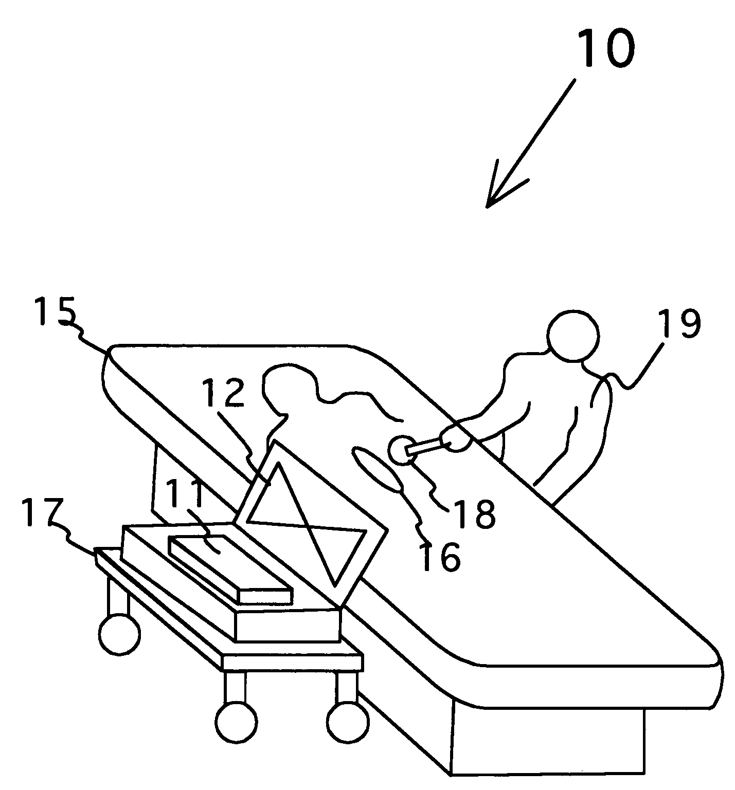
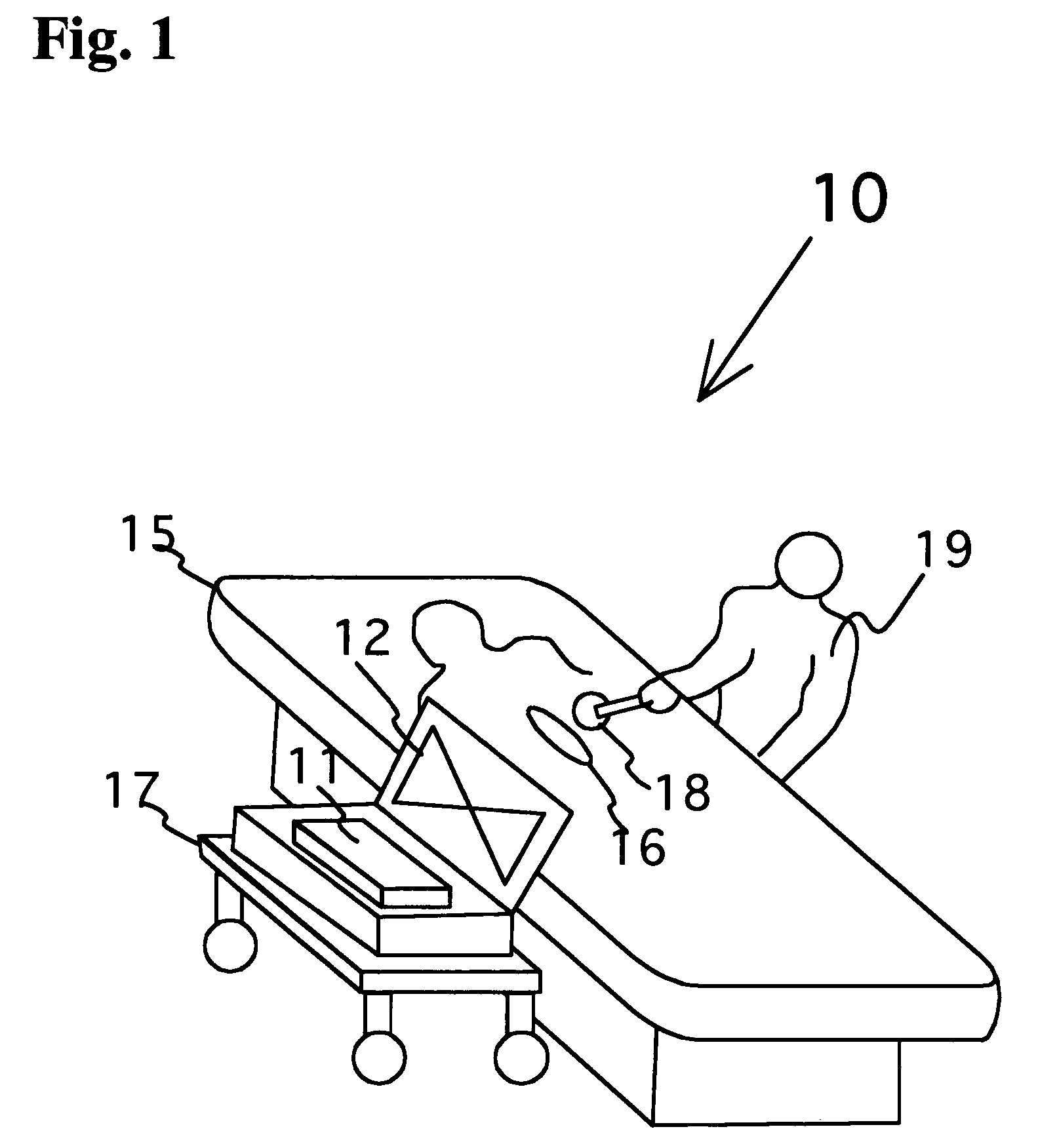
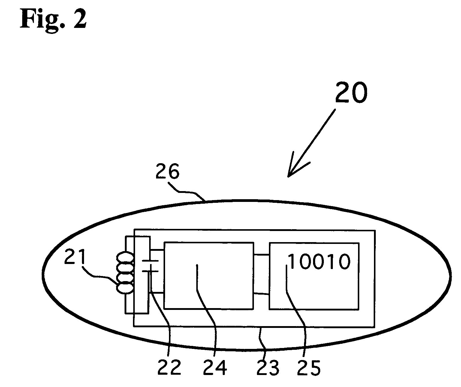
[0041]This invention relates to a surgical implement detector utilizing a radio-frequency identification marker which is embedded in a surgical sponge or laparotomy pad and is detected by a remote hand-held scanner or a fixed scanner. The scanner may be used to locate the so marked laparotomy pads or surgical sponges any time during surgery. More specifically, it is used to determine whether any foreign objects are left behind in a surgical cavity prior to surgical wound closure. The radio-frequency identification marker is an integrated circuit with a burned-in digital code in a read-only memory. It is powered by a capacitor circuit that is connected to an antenna, which comprises a ferrite element wound with copper wire. When the radio-frequency identification marker is in the presence of electromagnetic radiation, the antenna couples with the interrogating electromagnetic radiation, charges the capacitor and powers the integrated circuit, which accesses the burned-in digital code...


PUM


Abstract

A radio-frequency surgical implement detection system detects surgical implements in a surgical wound during and at the completion of a surgical procedure. Surgical implements, including surgical sponges or laparotomy pads, gauze pads and metallic surgical instruments, are individually attached to a non battery-powered, encapsulated radio-frequency marker. The marker comprises an integrated chip having a burnt-in memory code, which is broadcast through an antenna using a modulated carrier frequency. The code is received by an interrogating antenna of a detector. The interrogating antenna provides a power pulse, which is received by the antenna of the radio-frequency marker. The power pulse charges a capacitor, which proves power for the read function, carrier frequency modulation function and broadcast function of the integrated chip, permitting each marker-containing implement to be specifically identified.

Description

BACKGROUND OF THE INVENTION[0001]1. Field of the Invention[0002]The present invention relates to radio-frequency identification (RFID) markers for detection of surgical implements; and more particularly, to use of an RFID marker embedded in or otherwise securely attached to a surgical implement, such as a laparotomy pad or sponge, metallic surgical instrument, or other implement, for preventing the inadvertent retention of such implement during a surgical procedure.[0003]2. Description of the Prior Art[0004]Many patents disclose methods for detection of surgical implements following surgery prior to wound closure. Such detection methods incorporate x-ray opaque markers within surgical implements and effect detection using postoperative x-ray of the patient or of discarded sponges. Also disclosed as being suitable for detection of surgical implements are methods involving use of resonant tags made from magnetomechanical elements, capacitors, LRC oscillatory circuits and smart markers...

Claims


Application Information

Patent Timeline
Patent Type & Authority Patents(United States)
IPC IPC(8): G08B13/14
CPCA61B5/06A61B19/44A61B2019/448A61B90/90A61B90/98
Inventor FABIAN, CARL E.NARASIMHAN, DAVE
Owner FABIAN CARL E
Why Eureka
Try Eureka