Friction reducing lubricant for stent loading and stent delivery systems

a lubricant and stent technology, applied in the field of stents, can solve the problems of high frictional force on the stent, damage to the stent and/or the stent delivery system, and increase the forces inherent in loading, so as to reduce the risk of stent damage, increase the inherent forces of loading, and high frictional force

Inactive Publication Date: 2007-12-18
CARDINAL HEALTH SWITZERLAND 515 GMBH
View PDF18 Cites 48 Cited by
  • Summary
  • Abstract
  • Description
  • Claims
  • Application Information

AI Technical Summary

Benefits of technology

[0020]The loading of a self-expanding stent into a stent delivery system places high frictional forces on the stent. These frictional forces may cause damage to the stent and/or the stent delivery system. In addition, the coating of the stents with polymers and/or therapeutic agents may increase the forces i

Problems solved by technology

The loading of a self-expanding stent into a stent delivery system places high frictional forces on the stent.
These frictional forces may cause damage to the st

Method used


Image

  • Friction reducing lubricant for stent loading and stent delivery systems
  • Friction reducing lubricant for stent loading and stent delivery systems
  • Friction reducing lubricant for stent loading and stent delivery systems

Examples


Embodiment Construction

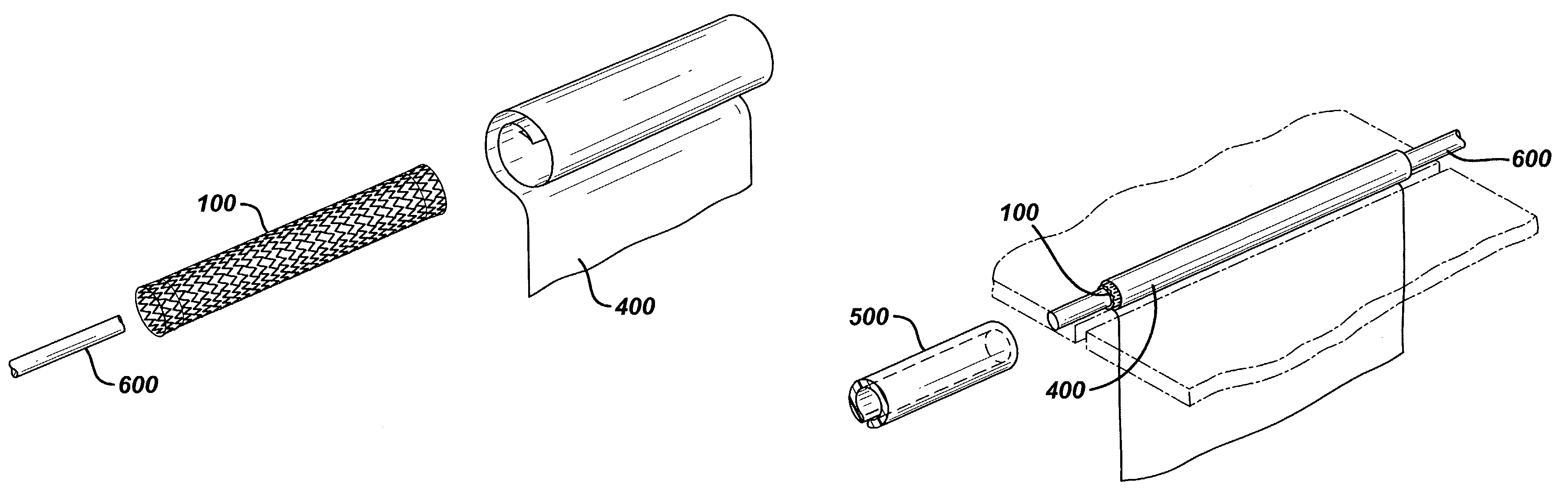
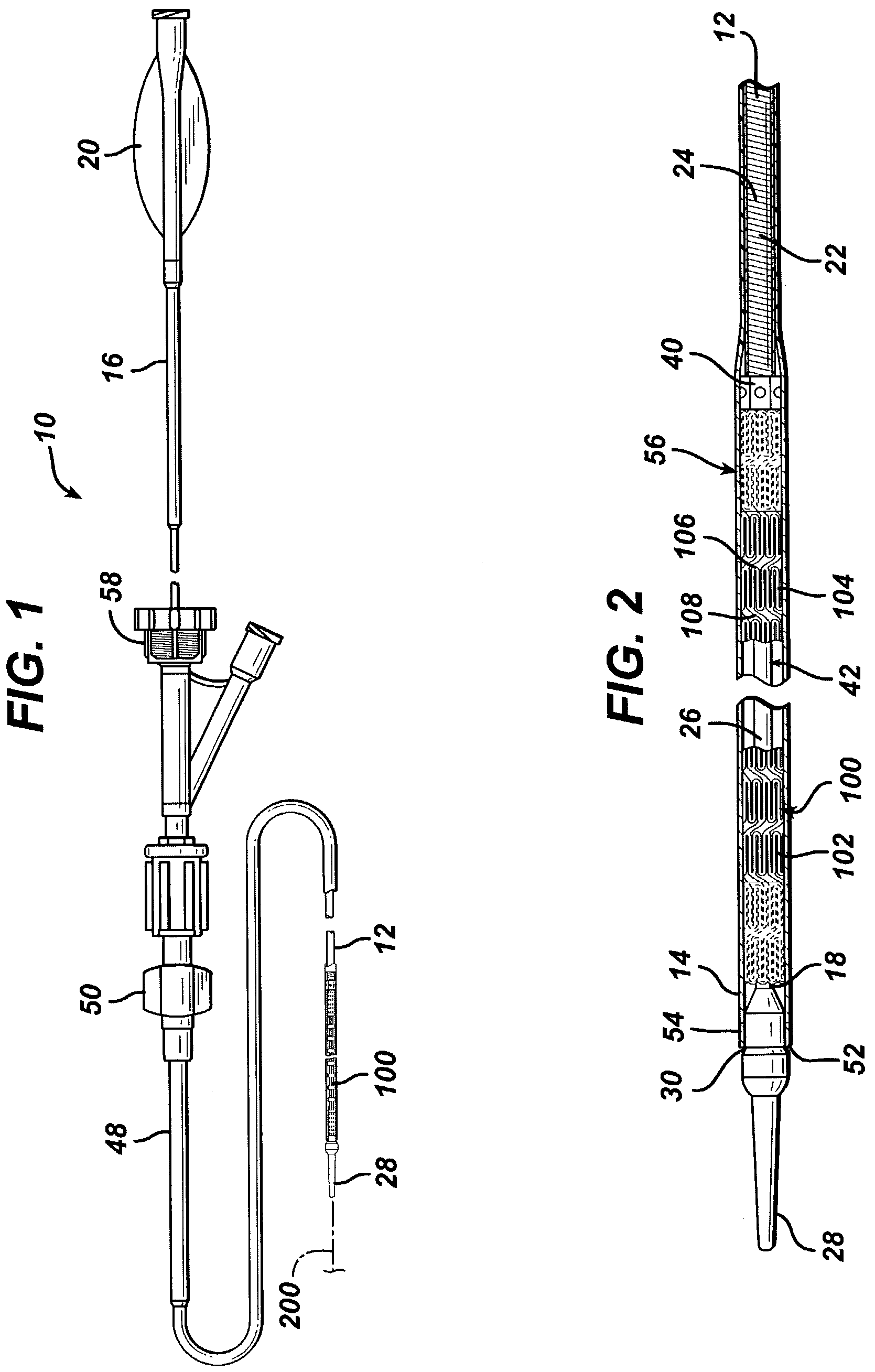
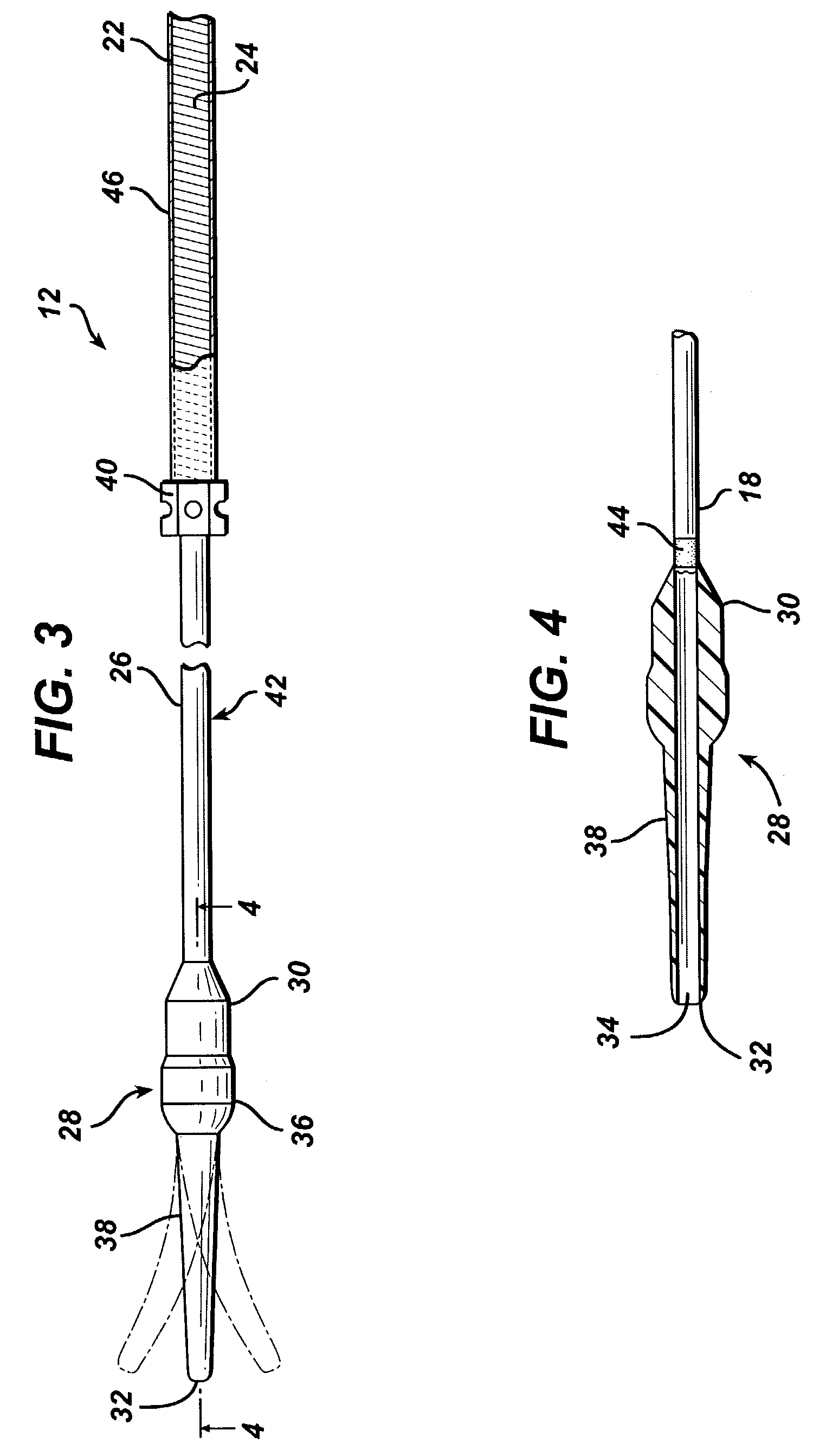
[0033]FIGS. 1 and 2 illustrate an exemplary self-expanding stent delivery apparatus 10 in accordance with the present invention. Apparatus 10 comprises inner and outer coaxial tubes. The inner tube is called the shaft 12 and the outer tube is called the sheath 14. A self-expanding stent 100 is located within the sheath 14, wherein the stent 100 makes frictional contact with the sheath 14 and the shaft 12 is disposed coaxially within a lumen of the stent 100.

[0034]Shaft 12 has proximal and distal ends 16 and 18 respectively. The proximal end 16 of the shaft 12 has a Luer guidewire hub 20 attached thereto. As seen best from FIG. 10, the proximal end 16 of the shaft 12 is preferably a ground stainless steel hypotube. In one exemplary embodiment, the hypotube is stainless steel and has a 0.042 inch outside diameter at its proximal end and then tapers to a 0.036 inch outside diameter at its distal end. The inside diameter of the hypotube is 0.032 inch throughout its length. The tapered o...


PUM


Abstract

A system for loading self-expanding stents into a stent delivery system that comprises a lubricious coating on one or more components to substantially reduce the frictional forces associated with loading stents. The stents may be bare or coated stents. The lubricious coating comprises glycerol.

Description

FIELD OF THE INVENTION[0001]The present invention relates to stents for use within a body passageway or duct, which are particularly useful for repairing blood vessels narrowed or occluded by disease, and more particularly, to systems for delivering such stents.BACKGROUND OF THE INVENTION[0002]Various endoprosthesis assemblies, which include expandable stents, have been proposed or developed for use in association with angioplasty treatments and other medical procedures. The endoprosthesis assembly is generally percutaneously routed to a treatment site and the stent is expanded to maintain or restore the patency of a body passageway such as a blood vessel or bile duct. A stent is typically cylindrical in shape comprising an expandable open frame. The stent will typically expand either by itself (self-expanding stents) or will expand upon exertion of an outwardly directed radial force on an inner surface of the stent frame by a balloon catheter or the like.[0003]Stents for endovascul...

Claims


Application Information

Patent Timeline
IPC IPC(8): A61F2/06A61F2/84A61F2/82
CPCA61F2/95A61F2002/9522A61F2/9522A61F2/9526
Inventor JACKSON, KAREN PAULETTEWIDENHOUSE, CHRISTOPHER WILLIAM
Owner CARDINAL HEALTH SWITZERLAND 515 GMBH
Why Eureka
Try Eureka