Boundary acoustic wave filter

a filter and boundary acoustic technology, applied in the field of boundary acoustic filter, can solve the problems of increasing the cost increasing the size of the surface acoustic wave device, and propagating loss of boundary acoustic waves, etc., and achieve satisfactory frequency characteristics and reduce the effect of siz

Active Publication Date: 2007-12-18
MURATA MFG CO LTD
View PDF14 Cites 31 Cited by
  • Summary
  • Abstract
  • Description
  • Claims
  • Application Information

AI Technical Summary

Benefits of technology

[0016]To overcome the problems described above, preferred embodiments of the present invention provide a boundary acoustic wave filter having a reduced size, wherein when the filter defines a transmission filter or a reception filter of radio equipment, a satisfactorily large attenuation is provided in the stopband, and the filter has a satisfactory frequency characteristic.
[0037]In the above communication device or the duplexer, when the boundary acoustic wave filter according to preferred embodiments of the present invention is used as the filter in which the center frequency is relatively low, preferably, in the stopband at the high-frequency side of the passband of the filter in which the center frequency is relatively low, when the product of the wavelength λ determined by the period of the electrodes and the frequency at the higher end of the passband of a counterpart filter, in which the center frequency is relatively high, is less than the sound velocity of the slow transverse waves, the following advantage is provided. That is, in the filter characteristic of the filter in which the center frequency is relatively low, a sufficient attenuation is ensured in the high-frequency side of the passband, i.e., in the frequency range extending to the higher end of the passband of the counterpart filter in which the center frequency is relatively high. Accordingly, a duplexer and a communication device in which the attenuation in the stopband is ensured over a sufficient frequency range are provided.

Problems solved by technology

The use of such a package including a cavity inevitably increases the cost of the surface acoustic wave device.
Furthermore, since the dimensions of the package are significantly larger than the dimensions of the surface acoustic wave element, the size of the surface acoustic wave device is inevitably increased.
These leaked components cause propagation loss of the boundary acoustic waves.
Where a boundary acoustic wave device is used as the transmission filter and the reception filter, as described above, even when a boundary acoustic wave filter is prepared under conditions in which the propagation loss is sufficiently reduced, it is difficult to achieve a satisfactory frequency characteristic.
Even if the loss is reduced by eliminating a leakage component only in the passband to reduce the propagation loss, when a leakage component is present in the attenuation band disposed at the high-frequency side of the passband, the electric power of the attenuation band is directly transmitted by the leakage component from the input port to the output port, resulting in an insufficient attenuation.
Consequently, it is difficult to achieve a satisfactory frequency characteristic.
Accordingly, when a boundary acoustic wave filter is used as the transmission filter and the reception filter, particularly in the transmission filter, the attenuation in the stopband disposed at the high-frequency side of the passband, that is, in the passband of the reception filter is not satisfactory.

Method used


Image

  • Boundary acoustic wave filter
  • Boundary acoustic wave filter
  • Boundary acoustic wave filter

Examples


Embodiment Construction

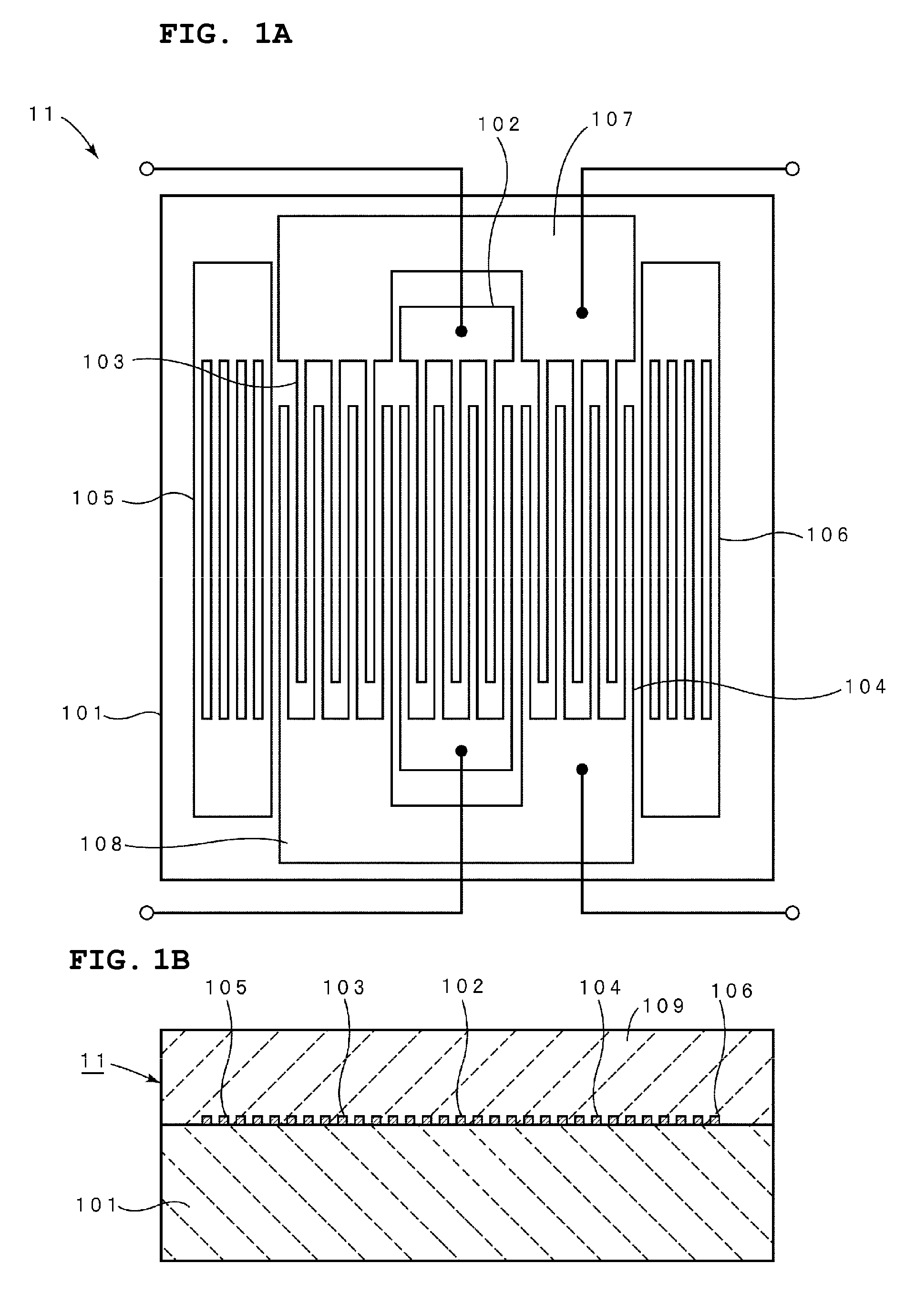
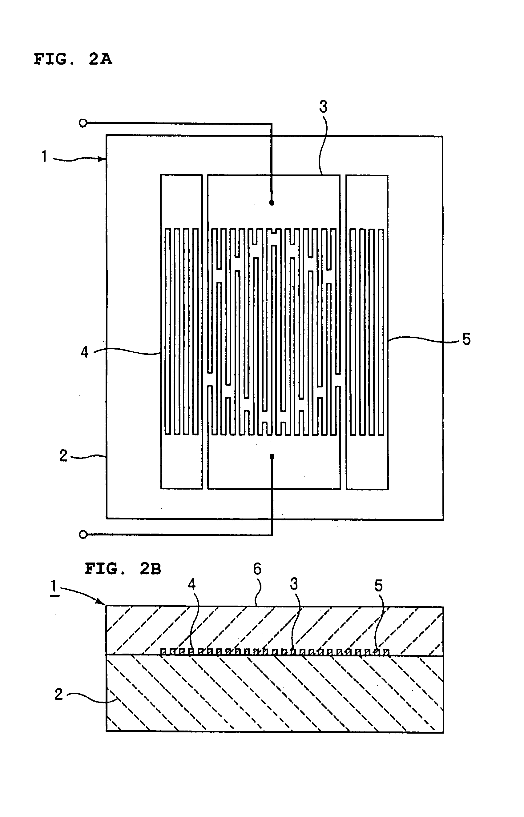
[0056]Preferred embodiments of a boundary acoustic wave filter of the present invention will now be described with reference to the drawings.

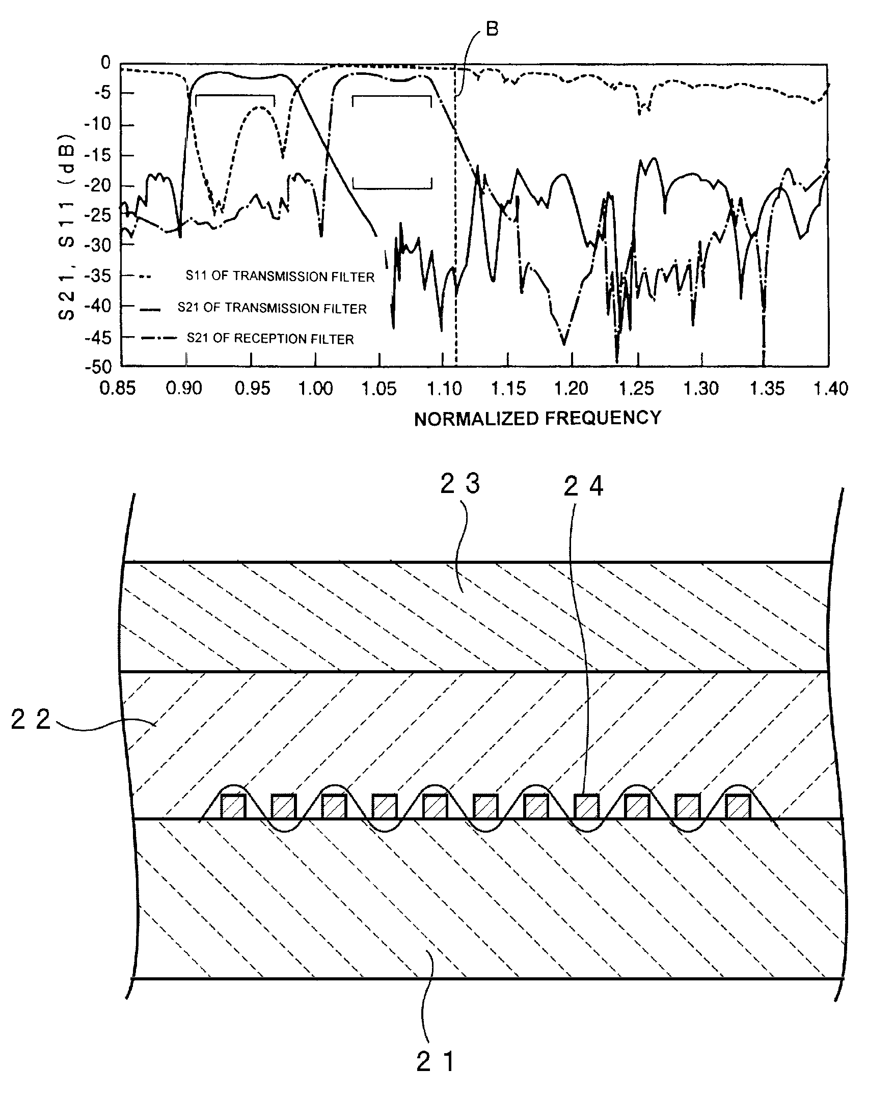
[0057]When the sound velocity of boundary acoustic waves is controlled to be less than the sound velocity of slow transverse waves propagating through a first medium layer and a second medium layer, the energy of the boundary acoustic waves is concentrated near electrodes disposed in the boundary, thus obtaining a condition in which the propagation loss is zero. Consequently, a transmission filter and a reception filter, whose target frequency characteristics are shown in FIG. 15, were prepared using boundary acoustic wave filters. In FIG. 15, the range represented by frequencies FL1 to FL2 is the transmission side passband, and the range represented by frequencies FH1 to FH2 is the reception side passband, wherein FH1>FL2.

[0058]The normalized frequency of FL1 was about 0.91, the normalized frequency of FL2 was about 0.97, the normalized freque...


PUM


Abstract

A boundary acoustic wave filter includes a first medium layer, a second medium layer laminated on the first medium layer, and IDT electrodes that are disposed at the boundary between the first and second medium layers and that define an electroacoustic transducer. In the boundary acoustic wave filter, the sound velocity of boundary acoustic waves, which is the product of the wavelength determined by the period of the electrodes and the frequency at least the lower end of the stopband disposed at the high-frequency side of the passband, is less than the sound velocity of slow transverse waves propagating through the first medium layer and the second medium layer.

Description

BACKGROUND OF THE INVENTION[0001]1. Field of the Invention[0002]The present invention relates to a boundary acoustic wave filter used as, for example, a bandpass filter of communication equipment. More specifically, the present invention relates to a boundary acoustic wave filter that utilizes boundary acoustic waves propagating along the boundary between a first medium layer and a second medium layer.[0003]2. Description of the Related Art[0004]Various surface acoustic wave devices have been used as an RF filter and an IF filter for cell phones, a resonator for VCOs, a VIF filter for televisions, and other suitable devices. The surface acoustic wave devices utilize surface acoustic waves such as Rayleigh waves or first leaky waves that propagate on the surface of a medium.[0005]Since surface acoustic waves propagate on the surface of a medium, they are sensitive to changes in the surface condition of the medium. Accordingly, in order to protect the surface of the medium on which su...

Claims


Application Information

Patent Timeline
Patent Type & Authority Patents(United States)
IPC IPC(8): H03H9/46H03H9/70H03H9/64H03H9/72H03H9/00H03H9/02H03H9/25
CPCH03H9/0222
Inventor KANDO, HAJIME
Owner MURATA MFG CO LTD
Why Eureka
Try Eureka