
Method and system for using optical phase conjugation in an optical communications network

a technology of optical phase and optical communication network, applied in data switching network, frequency-division multiplex, instruments, etc., can solve problems such as resonance effects, inter-symbol interference and bit errors, and deterioration of signal quality

Active Publication Date: 2007-12-18
CIENA
View PDF14 Cites 10 Cited by
  • Summary
  • Abstract
  • Description
  • Claims
  • Application Information

AI Technical Summary

Problems solved by technology

Since a bit contains many wavelengths traveling at different speeds, the bit tends to distort as it travels along the transmission fiber resulting in inter-symbol interference and bit errors.
Non-linear effects also induce crosstalk and deteriorate signal quality.
While this technique of compensating dispersion does negate XPM and SPM effects in amplitude-modulated channels, it can cause resonance effects since all signals are compressed back to their start positions and are also all aligned in time (i.e., there is no time skew between signals).
A second complication of this solution that arises in multi-channel systems is the inability to perfectly match the dispersion slopes of the transmission fiber and dispersion compensating fiber.
A third problem with mitigating XPM and SPM effects with perfect per-span dispersion compensation is the distributed nature of SPM and XPM generation.
A fourth problem with mitigating SPM and XPM effects are non-overlapping dispersion optimization points for SPM compensation and XPM compensation.
For all these reasons, as transmission distances increase, it becomes more difficult to mitigate XPM and SPM generated noise by simple dispersion compensation or dispersion mapping.
None of the known techniques offers a solution that neutralizes non-linear effects that are present after all of the commonly used solutions are used.

Method used


Image

  • Method and system for using optical phase conjugation in an optical communications network
  • Method and system for using optical phase conjugation in an optical communications network
  • Method and system for using optical phase conjugation in an optical communications network

Examples


Embodiment Construction

[0022]The following detailed description of the invention refers to the accompanying drawings. The same reference numbers in different drawings identify the same or similar elements. Also, the following detailed description does not limit the invention. Instead, the scope of the invention is defined by the appended claims and equivalents thereof.

[0023]The expression “optically communicates” as used herein refers to any connection, coupling, link or the like by which optical signals carried by one optical device are imparted to the “communicating” device. Such “optically communicating” devices are not necessarily directly connected to one another and may be separated by intermediate optical components or devices. Likewise, the expressions “connection” and “operative connection” as used herein are relative terms and do not require a direct physical connection.

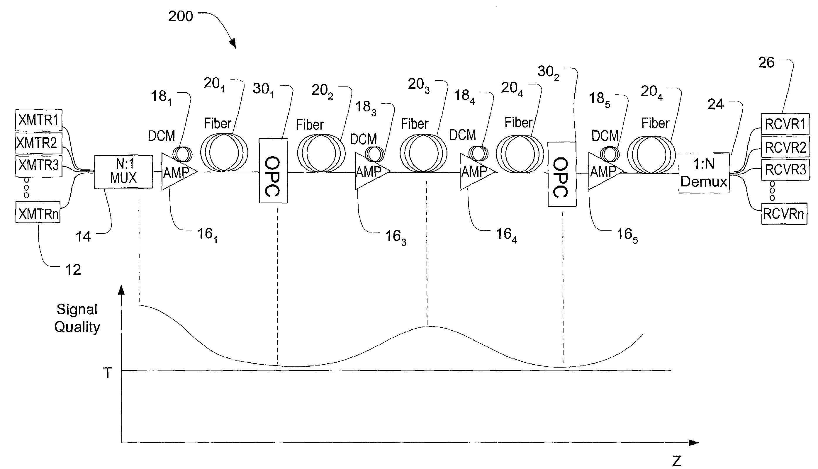
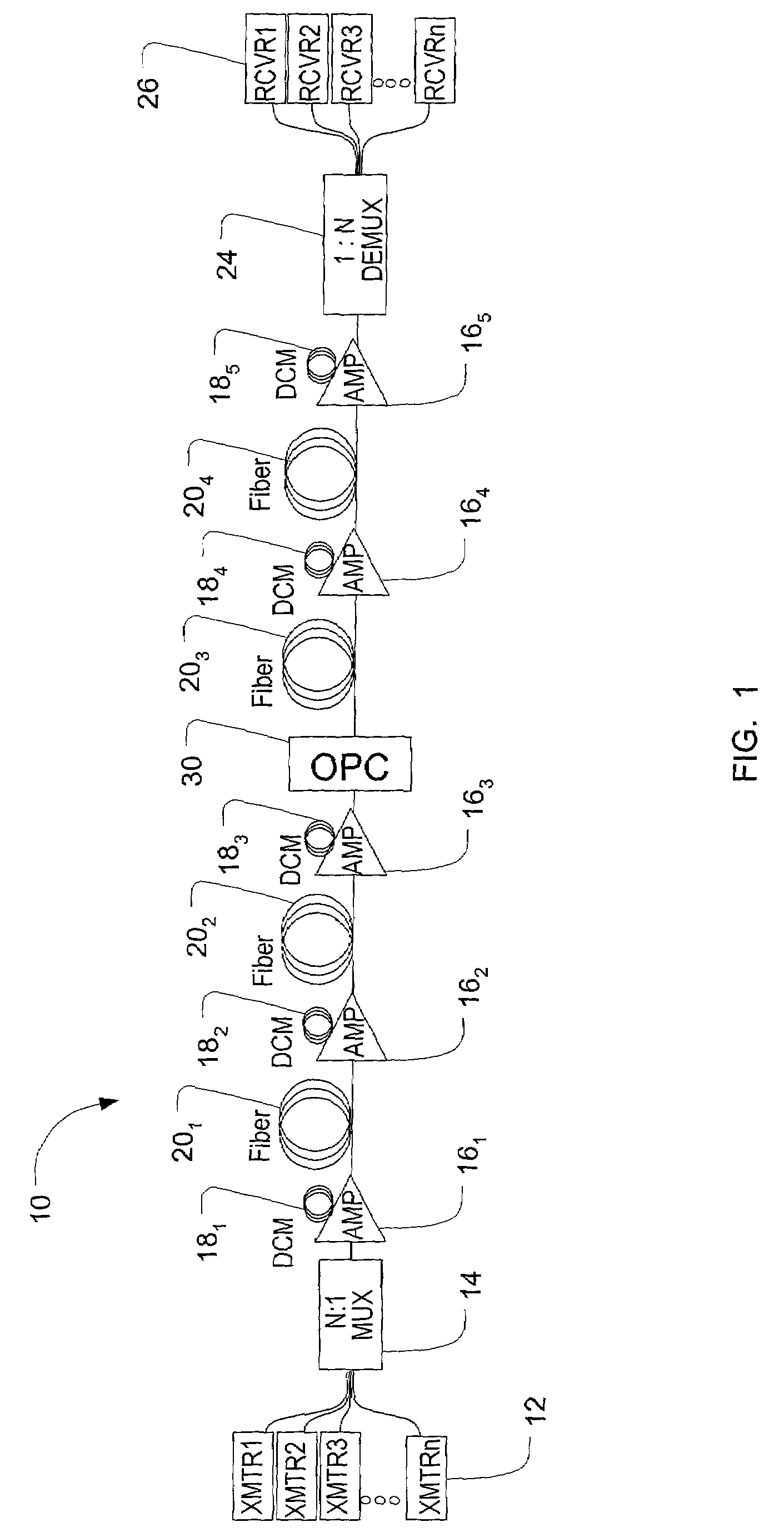
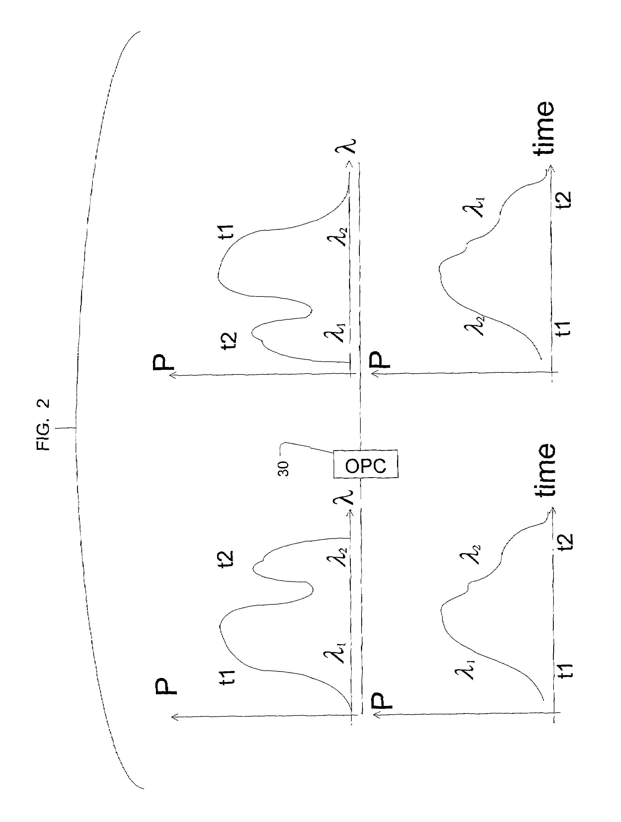
[0024]FIG. 1 depicts an optical communications network 10 in an exemplary embodiment of the invention. The network 10 includes ...


PUM


Abstract

A optical communications network including at least one optical phase conjugator for compensating for non-linear effects. The optical communications network includes at least one dispersion compensation module before the optical phase conjugator and at least one dispersion compensation module after the optical phase conjugator. The dispersion compensation modules compensate for linear effects of the transmission path such as dispersion and dispersion slope. This allows the optical phase conjugator to be designed to compensate for non-linear effects such as self-phase modulation and cross-phase modulation. The separate compensation of linear and non-linear effects provides enhanced control of these effects.

Description

BACKGROUND OF THE INVENTION[0001]1. Field of Invention[0002]This invention relates to a method and system for using optical phase conjugation in an optical communications network.[0003]2. Description of Related Art[0004]Fiber-optic communication networks are experiencing rapidly increasing deployment. Especially rapid is the growth of segments that carry multi-gigabit digital data on multiple wavelengths over a single fiber strand, which are known as wavelength division multiplexing (WDM). The wavelength channel density (i.e., the number of channels carried by one fiber) and the data rate carried on individual wavelengths continue to increase. Current systems employ 50 GHz channel spacing, but 25 GHz and 12.5 GHz channel spacings are expected to be utilized. Data rates of 10 Gbps are currently used, but 40 Gbps data rates are also expected. Both increased channel density and increased data rate contribute to increased crosstalk between channels.[0005]Several linear and non-linear ef...

Claims


Application Information

Patent Timeline
Patent Type & Authority Patents(United States)
IPC IPC(8): H04J1/16
CPCH04B10/25137H04J14/0221H04J14/0201
Inventor FRANKEL, MICHAEL Y.SARDESAI, HARSHAD P.
Owner CIENA
Learn More