

Cooled gas turbine transition duct
a transition duct and gas turbine technology, applied in the direction of machines/engines, stators, lighting and heating apparatus, etc., can solve the problem of temperature-limiting stress level
- Summary
- Abstract
- Description
- Claims
- Application Information
AI Technical Summary
Benefits of technology
Problems solved by technology
Method used
Image

Examples
Embodiment Construction
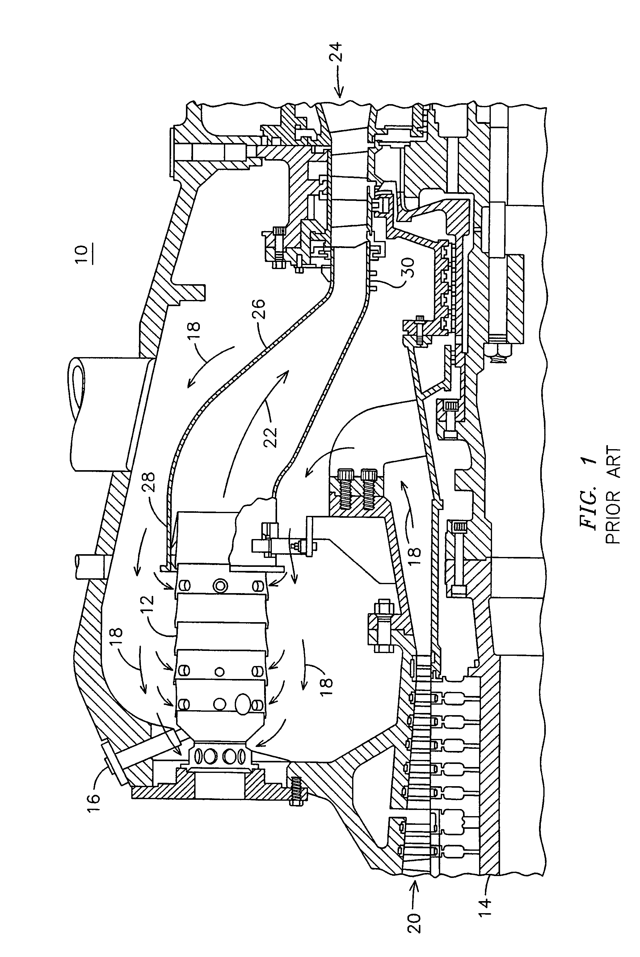
[0009]Model 251 gas turbine engines manufactured by the assignee of the present invention currently rely on a ceramic thermal barrier coating to limit the temperature of the material used to form the transition ducts. Refinements in the combustor design for this style of engine have increased the operating temperature of the transition ducts, thereby providing incentive for improvements in the cooling of the duct wall material.
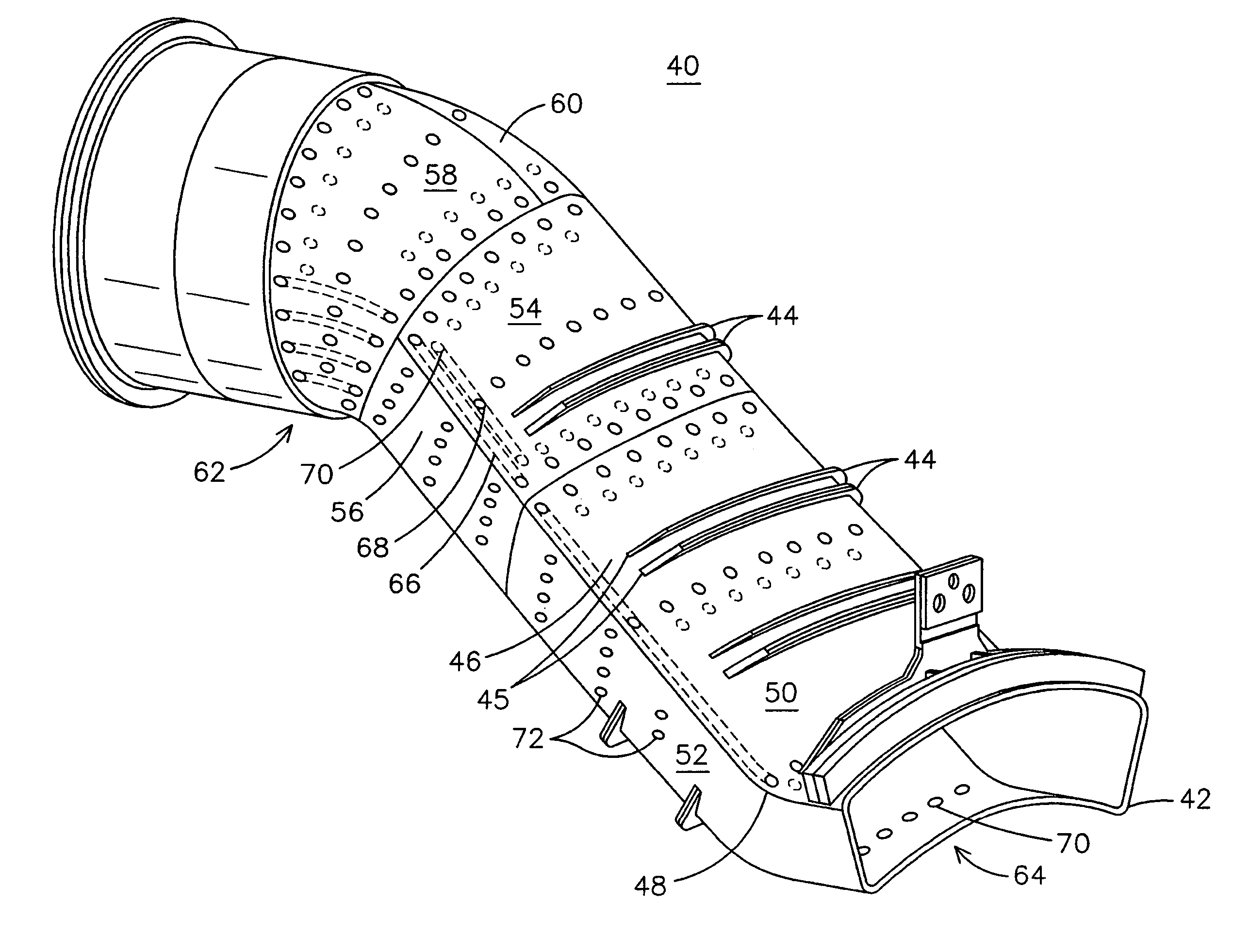
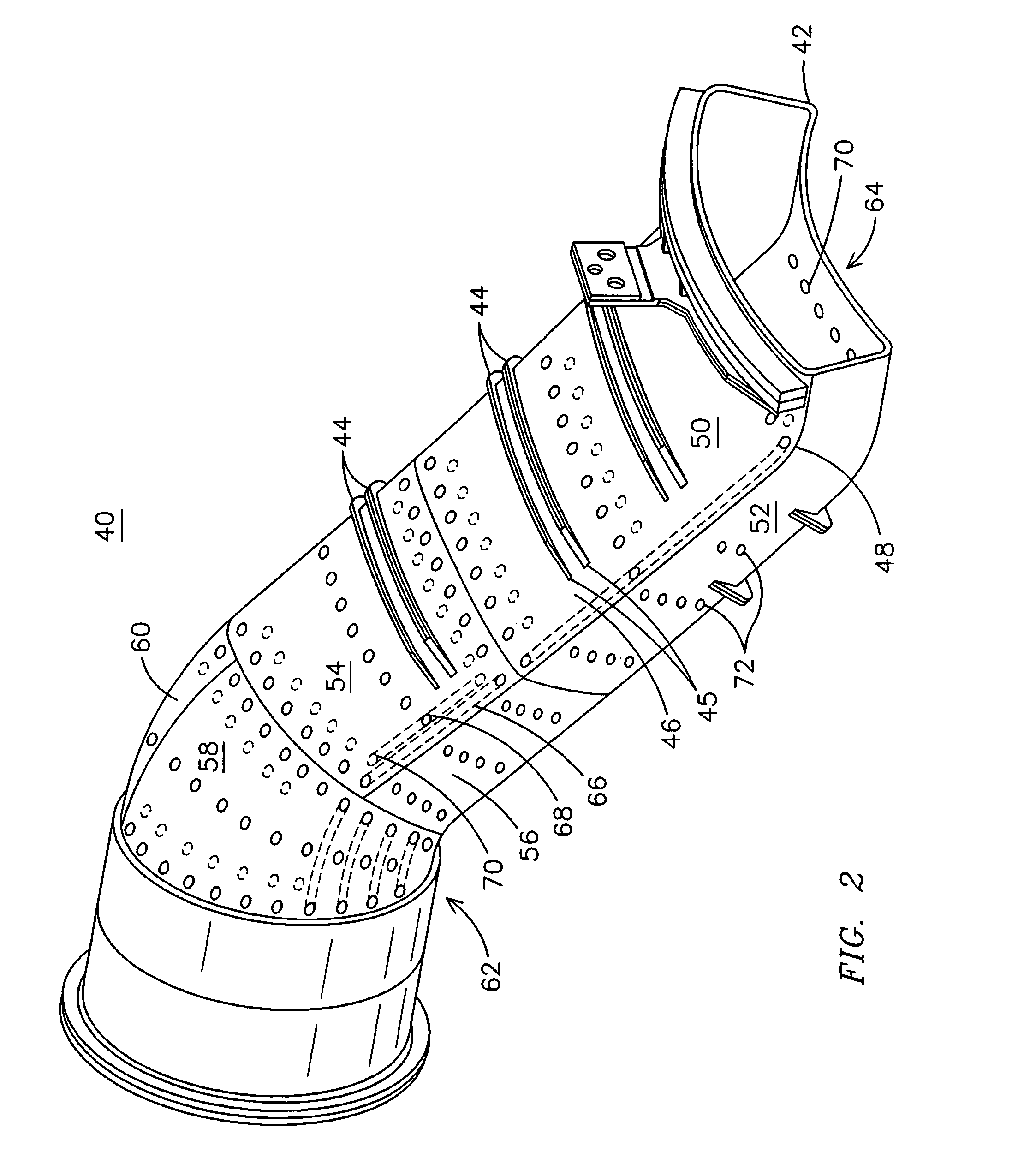
[0010]FIG. 2 is a perspective view of an improved transition duct 40 that may be used in a gas turbine engine such as a Model 251 engine, for example. This transition duct 40 innovatively combines strategically placed internal cooling channels and effusion cooling holes with selected areas of no active cooling to obtain an improved level of performance when compared to prior art designs.
[0011]Transition duct 40 is formed from a plurality of individual panels 50, 52, 54, 56, 58, 60. The panels are formed to a desired shape and then are joined such as by welding...
PUM
 Abstract
Description
Claims
Application Information