Compression connector assembly

a technology of compression connectors and connectors, applied in the direction of coupling contact members, coupling device connections, connection contact member materials, etc., can solve the problems of compression connectors, and aluminum compression connectors. , the majority of failures occur in aluminum compression connectors and conductors

Active Publication Date: 2007-12-25
HUBBELL INC
View PDF18 Cites 10 Cited by
  • Summary
  • Abstract
  • Description
  • Claims
  • Application Information

AI Technical Summary

Benefits of technology

[0017]Accordingly, a primary object of the present invention is to provide a compression connector assembly and a method of securing a cable having a bushing insert for providing an electrically clean and intimate current path from all layers of conductor stranding to the tubular bore of the bushing insert and connector.
[0018]Another object of the present invention is to provide a compression connector assembly and method of securing a cable which are relatively simple to assemble, use, and replace in comparison.
[0019]A further object of the present invention is to provide a compression connector and method of securing a cable with improved performance by reducing the number of actual interfaces, thereby enhancing the integrity of the connection and providing assurance of a low resistance interface with each layer of conductor stranding.
[0020]Yet another object of the present invention is to provide a compression connector with a reduced size, the shorter compression connector assembly reducing extrusion and birdcaging of the conductor stranding.

Problems solved by technology

Consequently, higher current levels result in much higher temperatures.
Therefore, compression connectors, are weak links in the system, and are failing at an increasing rate.
The majority of failures occur in aluminum compression connectors and conductors.
First, the vast majority of new connectors and conductors being installed are aluminum.
Second, high integrity aluminum connections are difficult to achieve due to oxidation.
Aluminum oxide is a highly effective electrical insulator, and is detrimental to the integrity of a compression connector on an aluminum conductor.
Conductivity of the electrical interface between the connector and the conductor is severely reduced when oxides are present.
The problem with this cleaning method is that it is highly time consuming and very difficult to accomplish in the field.
The process of unlaying the stranding of the conductor a sufficient distance from the end to allow cleaning of individual stranding is laborious and tedious.
While this method is possible in a typical laboratory condition, where the conductor may remain supported and still, the method is often unsuccessful in the field.
Performing the cleaning steps successfully on an aerial platform, such as a bucket truck, is highly improbable due to difficultly to dealing in handling the individual conductive strands.
Therefore, this method typically is not done in the field.
In addition, difficulties arise when the strands are re-layered into their original position.
Consequently, if the strands are not re-layered to provide the original diameter of the conductor as manufactured, the conductor cannot be inserted into the compression connector designed therefore.
Additionally, the above method does not solve the problem of the rapid formation of oxides.
However, the abrasive material will also wipe away the oil coating of the inhibitor designed to provide the oxygen barrier needed to prevent the re-growth of the oxide layer which the cleaner is attempting to remove.
However, this method works well only on the outer layer.

Method used


Image

  • Compression connector assembly
  • Compression connector assembly
  • Compression connector assembly

Examples


second embodiment

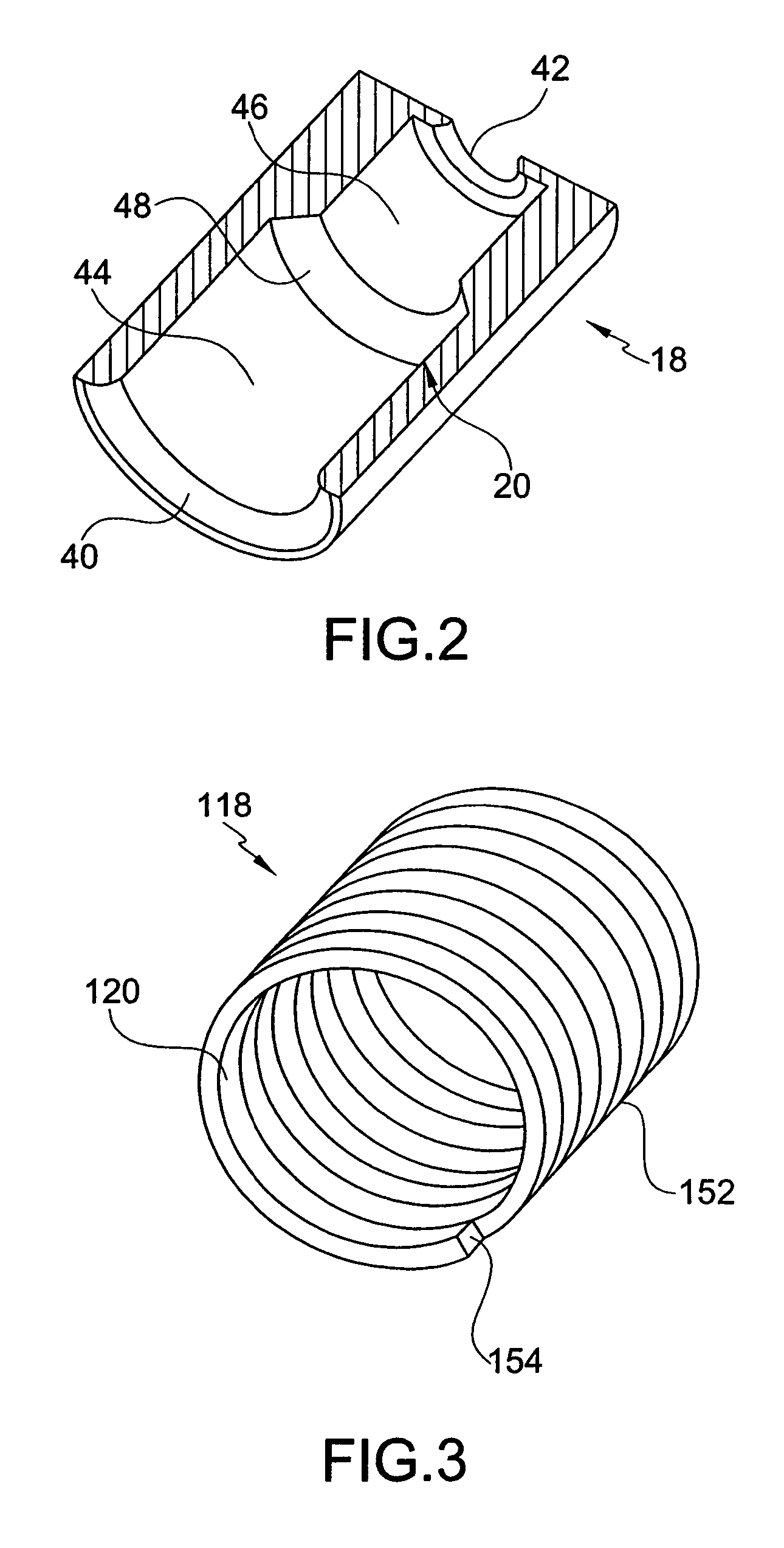
[0041]According to the invention, bushing insert 118 is depicted in FIG. 3. Tubular bore 120 of the bushing insert 118 is defined by a helically formed wire 152. Helically wound wire is preferably made of rectangular cross-section 154. However, the wire may be of any polygonal cross-section or could be made from a single piece of tubular material. Bushing insert 118 is capable of use with conductor stranding 14 having only two layers. The bushing insert 118 is sufficient to displace one layer of stranding.

third embodiment

[0042]According to the invention, FIG. 5 illustrates a unitary, one-piece compression connector assembly 210. Bushing insert 218 and gripping sleeve 228 are positioned substantially coaxial such that tubular bore 220 and inner recess 230 form a continuous cable securing passageway 234. Bushing insert 218 includes a conductor receiving end 224 and a conductor engagement end 226. Positioned between conductor receiving end 224 and conductor engagement end 226 is an inner diameter portion 244 and an outer diameter portion 246. A tapered diameter transition portion 245 extends outwardly from the inner diameter portion 244 to the outer diameter portion 246 and serves to guide the end of the strand layer into its respective bore.

[0043]Gripping sleeve 228 has an inner recess 230 and an outer surface 232, and is positioned adjacent to conductor engagement end 226. The unitary, one-piece compression connector assembly 210 reduces the number of parts required for assembly. Consequently, manufa...


PUM

PropertyMeasurementUnit
diameteraaaaaaaaaa
tensionaaaaaaaaaa
conductiveaaaaaaaaaa

Abstract

A compression connector assembly for securing a cable has a bushing insert and a gripping sleeve. The bushing insert includes a tubular bore, an exterior surface, a conductor receiving end, and a conductor engagement end. The gripping sleeve has an inner recess and an outer surface, and is adjacent to the conductor engagement end. The tubular bore and the inner recess are substantially coaxial, defining a cable securing passageway.

Description

CROSS REFERENCE[0001]This application is related to U.S. patent application Ser. No. 10 / 988,838, concurrently filed herewith and entitled “Stepped Compression Connector,” of inventor Carl R. Tamm, the subject of which is hereby incorporated by reference.FIELD OF THE INVENTION[0002]The present invention relates to a compression connector assembly which reduces the detrimental effects of aluminum oxidation on electrical connections. The compression connector includes a bushing insert for providing an electrically clean and intimate current path from a cable to the tubular bore of a bushing insert.BACKGROUND OF THE INVENTION[0003]A compression connector typically includes a hollow tubular section which is deformed with a special tool. The tool compresses the outer periphery of an electrical connector onto a stranded electrical conductor.[0004]Typically, in transmission lines, stranded electrical conductors are utilized. Stranded electrical conductors have a steel core overlaid by one o...

Claims


Application Information

Patent Timeline
Patent Type & Authority Patents(United States)
IPC IPC(8): H01R9/05
CPCH01R4/20H01R4/183H01R4/62Y10T29/49885Y10T29/49874Y10T29/49927Y10T29/49929H01R11/05
Inventor TAMM, CARL R.
Owner HUBBELL INC
Why Eureka
Try Eureka