Method of rapid mold development for swimming pools, spas and ponds

Inactive Publication Date: 2007-12-25
LATHAM POOL PROD
View PDF9 Cites 10 Cited by
  • Summary
  • Abstract
  • Description
  • Claims
  • Application Information

AI Technical Summary

Benefits of technology

[0015]A fourth objective is to provide a method and components to dramatically reduce the cost in both labor and materials of producing new pool designs—allowing for size and shape offerings to be changed whenever a design change is desired.
[0016]A fifth objective is to provide a method and components to produce a pool, spa, or pond shell on the described mold with a surface finish that is non porous and easy to maintain and repair, but is textured to provide a surface, which replicates the matte finish of cementitious

Problems solved by technology

Construction of the mold is the critical and costly step in building FRP pools.
Because the mold has to be structurally rigid to maintain its shape, it requires significant reinforcing substructure.
In the case of constructing a swimming pool plug, it is often difficult to build a positive part, because the actual pool is a “negative” space.
In other words, it is difficult to build a model of a hole.
The disadvantages of this method are numerous.
The temporary mold itself is made from a wide range of materials with different thermal expansion coefficients and different thermal conductivity coefficients, which result in an uneven cure on the glass master.
This can lead to stress fractures and other imperfections due to shrinkage the glass master, especially over time.
Equally important, is that one does not get a good visual view of what the pool will look like until after the glass master is constructed.
This is well after most of the expense in producing the tooling has occurred.
This can lead to designs that are not ideal and further work on the glass master to correct these design flaws can compound the problem of deterioration of the glass master surface and reduce the ultimate longevity of the mold.
In this case the mold can suffer because of the non-uniform curing that occurs due to the various materials used in construction and the wide range of different thermal expa

Method used


Image

  • Method of rapid mold development for swimming pools, spas and ponds
  • Method of rapid mold development for swimming pools, spas and ponds
  • Method of rapid mold development for swimming pools, spas and ponds

Examples


Embodiment Construction

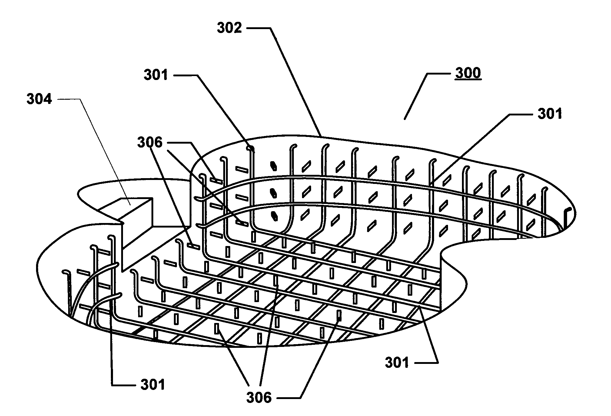
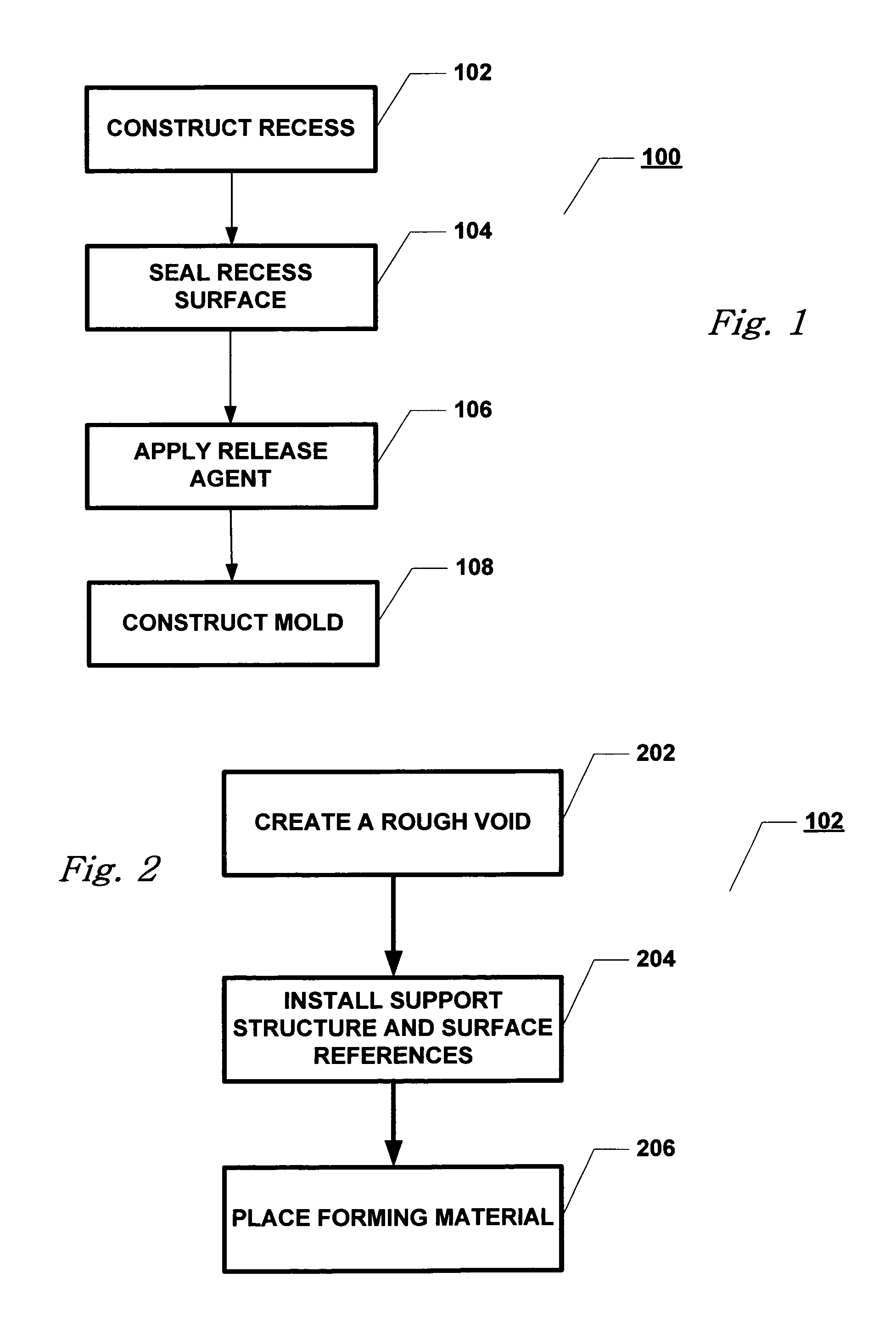
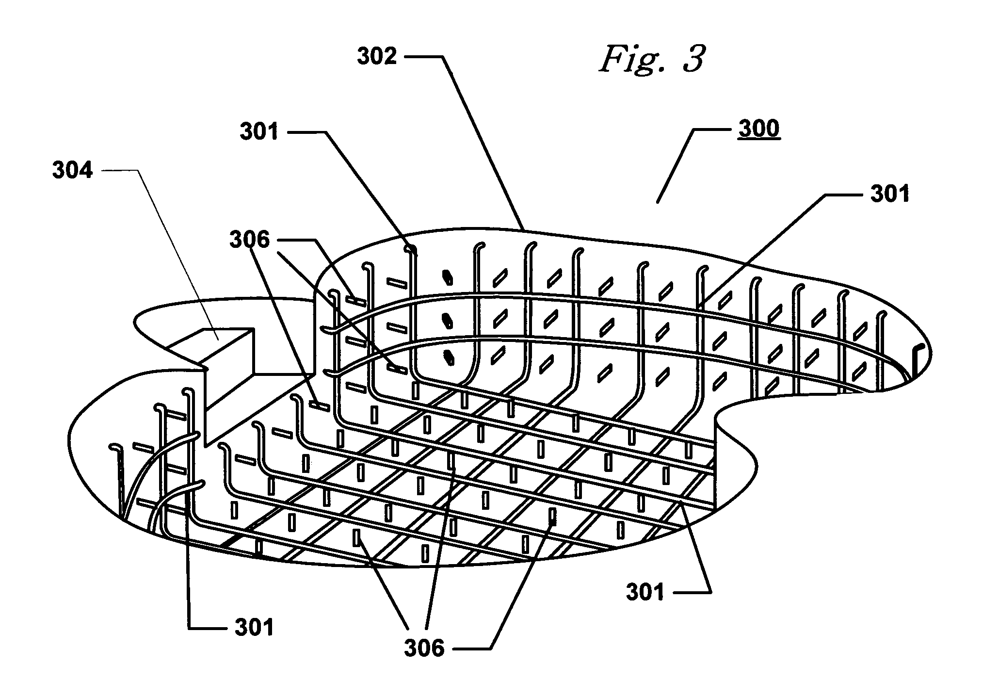
[0023]The various embodiments of the present invention and their advantages are best understood by referring to FIGS. 1 through 3 of the drawings. The elements of the drawings are not necessarily to scale, emphasis instead being placed upon clearly illustrating the principles of the invention. Throughout the drawings, like numerals are used for like and corresponding parts of the various drawings.

[0024]Before explaining the disclosed embodiment of the present invention in detail it is to be understood that the invention is not limited in its application to the details of the particular arrangement shown since the invention is capable of other embodiments. The detailed description set forth below in connection with the appended drawings is intended as a description of the presently preferred embodiment of the invention, and is not intended to represent the only form in which the present invention may be implemented or utilized. The description sets forth the sequence of steps and fun...


PUM

PropertyMeasurementUnit
Shapeaaaaaaaaaa
Thermal expansion coefficientaaaaaaaaaa

Abstract

A method for fabricating a pool mold comprising the steps of creating a recess, the recess having the general shape and contour of the desired finished pool and is installed with support materials and surface references. A layer of forming material is place over the support materials and surface references and formed to desired contour and grade. The forming material has substantially uniform coefficients of thermal expansion and heat transfer. The surface of the recess is sealed and coated with a release agent. A mold is then fabricated within the recess.

Description

CROSS-REFERENCES TO RELATED APPLICATIONS[0001]This application claims priority to U.S. Provisional Application No. 60 / 571,351 filed May 14, 2004 which is incorporated herein by reference.BACKGROUND[0002]1. Field[0003]The present invention relates generally to a method of forming a mold for a fiberglass reinforced plastic (FRP) swimming pool, spa, or pond, and specifically to a method for providing a rapid process for mold development.[0004]2. Description of the Related Art[0005]The desire to create artificial bodies of recreational water for swimming or landscape aesthetics has been around for centuries. The general concept of building a vessel in or above ground that can be used for swimming and other water sports has been a part of nearly every recorded society. There are three basic categories of swimming pool construction methods. The oldest and largest method involves forming a concrete shell in an excavated hole. The concrete maybe be poured as a monolithic slab, sprayed onto ...

Claims


Application Information

Patent Timeline
IPC IPC(8): B29C33/38
CPCE04H4/0081B29C33/40
Inventor CRONISE, IV, RAYMOND J.BAUDENDISTAL, THEODORE F.BLACK, JR., RICHARD E.
Owner LATHAM POOL PROD
Why Eureka
Try Eureka