Temperature sensor

a technology of temperature sensor and sensor body, which is applied in the field of temperature sensor, can solve the problem that the precision of the result cannot be increased, and achieve the effect of increasing the signal-noise ratio and the precision of the sensing resul

Inactive Publication Date: 2007-12-25
HIMAX TECH LTD
View PDF6 Cites 35 Cited by
  • Summary
  • Abstract
  • Description
  • Claims
  • Application Information

AI Technical Summary

Benefits of technology

[0009]One aspect of the invention is to provide a temperature sensor that can increase the signal-noise ratio and precision of the sensing result.
[0014]Accordingly, because the switching capacitors switch between the first / second predetermined voltages and ground when the temperature-dependent element switches between the first / second current source, output voltages on the first / second comparator output terminals is affected thereof. Thus, those skilled in the art could easily map a chosen temperature range to a chosen voltage range, and the signal-noise ratio and precision of the sensed result could be easily designed.

Problems solved by technology

Accordingly, only part of the sensing range (1.9V˜3.3V) is used to represent a temperature range −40˜127, and therefore precision of the result cannot be increased due to the limitation.

Method used


Image

  • Temperature sensor
  • Temperature sensor
  • Temperature sensor

Examples


Embodiment Construction

[0021]Reference will now be made in detail to the present preferred embodiments of the invention, examples of which are illustrated in the accompanying drawings. Wherever possible, the same reference numbers are used in the drawings and the description to refer to the same or like parts.

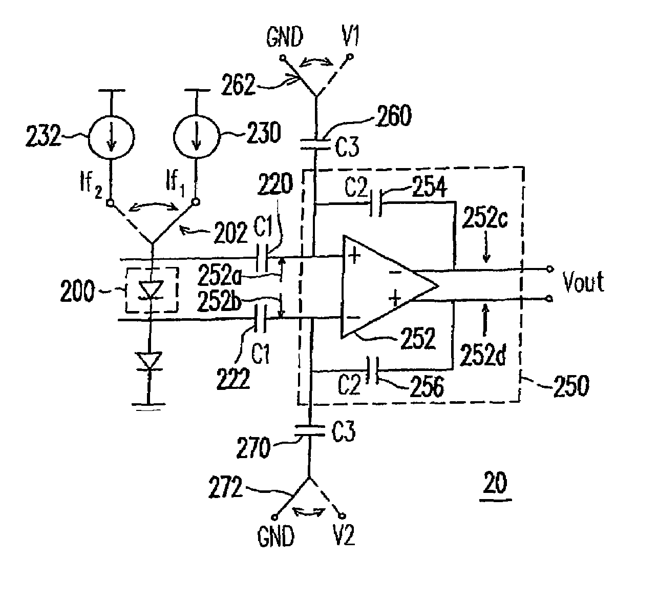
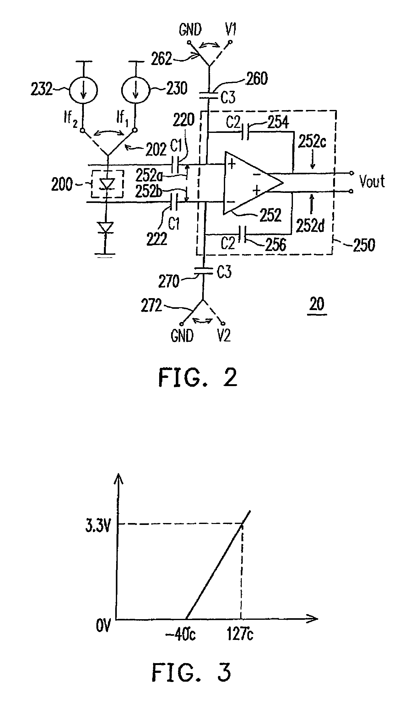
[0022]Referring to FIG. 2, a circuit diagram of a temperature sensor according to one embodiment of the present invention is shown therein. In the embodiment, temperature sensor 20 comprises a temperature-dependent element 200, a comparator unit 250, capacitors 220 / 222 and switching capacitors 260 / 270 (hereinafter, capacitors), wherein the comparator unit 250 comprises a comparator 252 and feedback capacitors 254 / 256 (hereinafter, capacitors). The temperature-dependent element 200 is an element that the voltage difference between input terminal and output terminal is related, for example, either proportional or inverse proportional, to the temperature. Although the temperature-dependent element 200 i...


PUM


Abstract

A temperature sensor, which comprises a temperature-dependent element, a comparator unit, first / second capacitors and first / second switching capacitors, is provided. The temperature-dependent element has an input terminal selectively coupled to one of a first current source and a second current source, and has an output terminal. The comparator unit comprises a comparator and first / second feedback capacitors. One end of the first switching capacitor is coupled to the first comparator input terminal, and another end of the first switching capacitor is selectively coupled to one of two different voltages. One end of the second switching capacitor is coupled to the second comparator input terminal, and another end of the second switching capacitor is selectively coupled to one of two different voltages.

Description

BACKGROUND OF THE INVENTION[0001]1. Field of Invention[0002]The present invention relates to a temperature sensor. More particularly, the present invention relates to a temperature sensor which having two capacitors coupled to temperature-independent voltage sources for increasing S / N ratio of the temperature sensor.[0003]2. Description of Related Art[0004]Recently, bipolar transistors or diodes are used as temperature sensors in CMOS technique. FIG. 1A shows a conventional temperature sensor. In the temperature sensor 10, the diode is selectively connected to two current sources 130 and 132 by using a switch 102. During operation, the diode 100 is connected to the current source 130 to receive the current If1. The voltage difference ΔV between capacitors 120 and 122, each of which has a capacitance C1, can be obtained by the following equation:[0005]Δ⁢⁢V=kTq=ln⁡(If1 / Is)[0006]Accordingly, after connecting diode 100 to the current source 130, the diode 100 is connected to the current...

Claims


Application Information

Patent Timeline
Patent Type & Authority Patents(United States)
IPC IPC(8): H01L35/00
CPCG01K7/01
Inventor YANG, HUNG-MING
Owner HIMAX TECH LTD
Why Eureka
Try Eureka