Temperature sensor

Inactive Publication Date: 2007-12-25
AMPHENOL THERMOMETRICS
View PDF4 Cites 17 Cited by
  • Summary
  • Abstract
  • Description
  • Claims
  • Application Information

AI Technical Summary

Benefits of technology

[0004]Embodiments of this invention provide a cost-effective, more robust and reliable temperature sensor capable of withstanding high temperat

Problems solved by technology

In high temperature areas or “hot zones”, operation of such devices is problematic.
Such efforts result in a more costly temperature sensor, however, and/or a temperature sensor which still may degrade and become unreliable after a relatively s

Method used


Image

  • Temperature sensor
  • Temperature sensor
  • Temperature sensor

Examples


Embodiment Construction

[0019]Aside from the preferred embodiment or embodiments disclosed below, this invention is capable of other embodiments and of being practiced or being carried out in various ways. Thus, it is to be understood that the invention is not limited in its application to the details of construction and the arrangements of components set forth in the following description or illustrated in the drawings. If only one embodiment is described herein, the claims hereof are not to be limited to that embodiment. Moreover, the claims hereof are not to be read restrictively unless there is clear and convincing evidence manifesting a certain exclusion, restriction, or disclaimer.

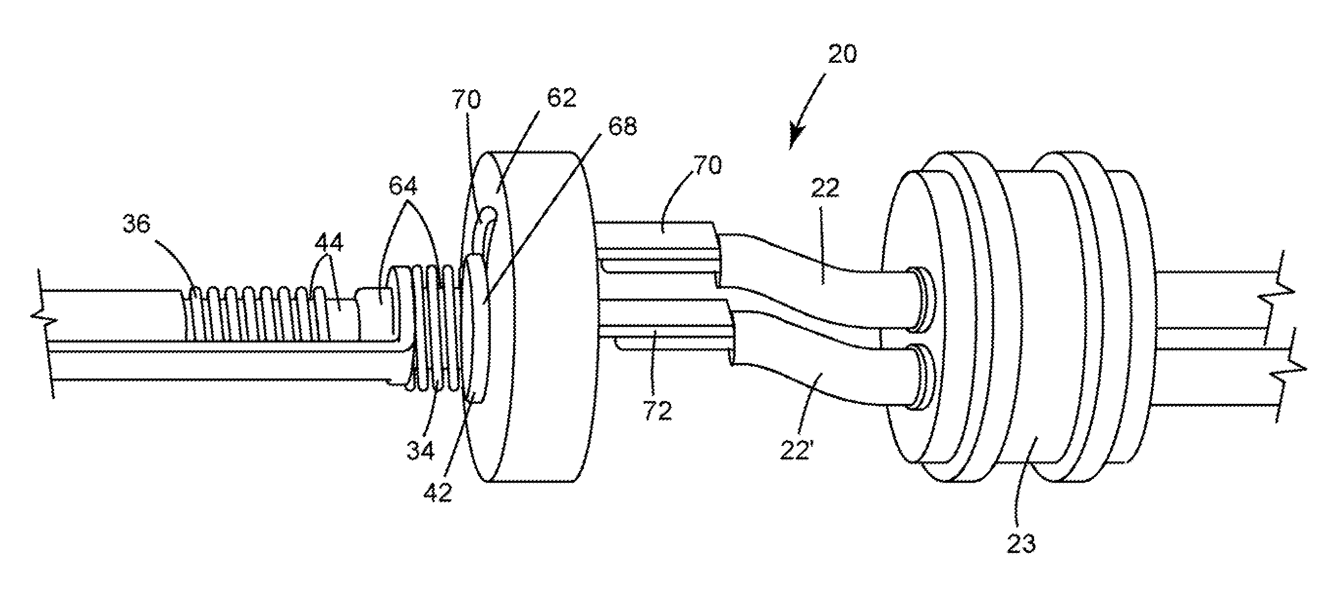
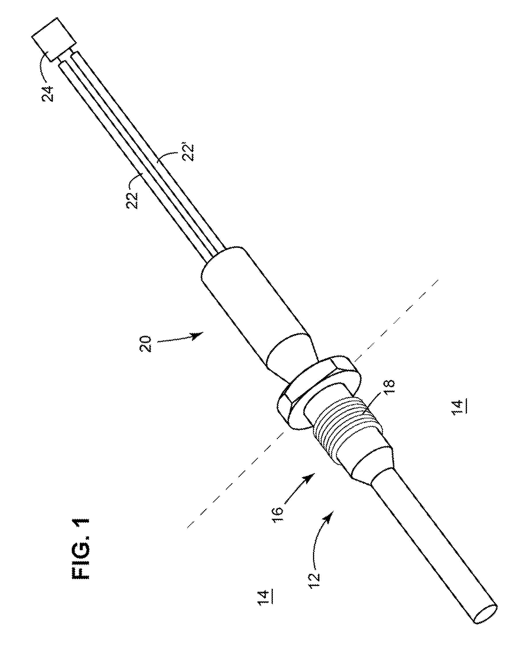
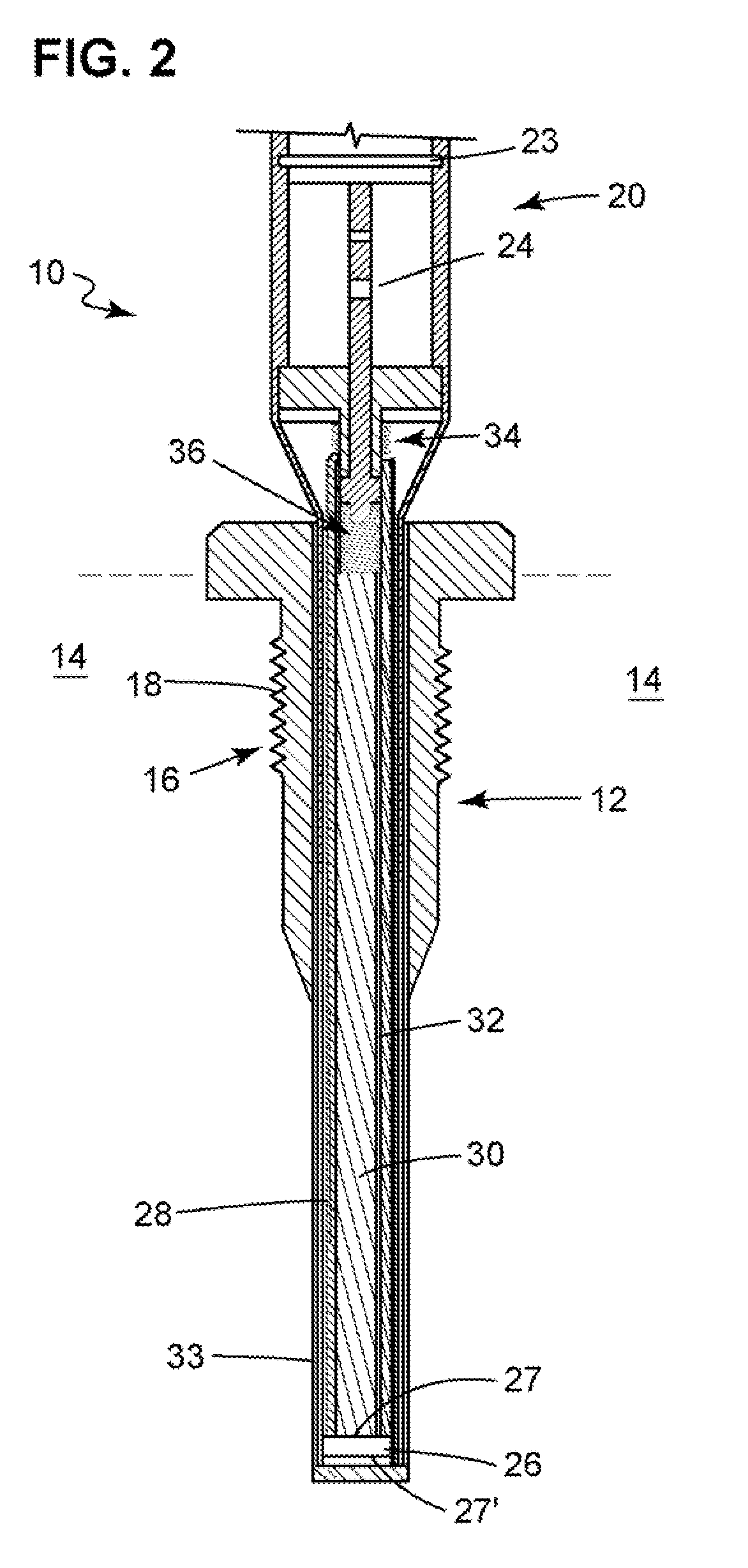
[0020]Temperature sensors which are subjected to very high temperatures and frequently undergo extreme temperature variations often degrade and / or consequently become ineffective over time, as discussed in the Background section. The subject invention offers an improved temperature sensor better able to withstand such extre...


PUM


Abstract

A temperature sensor includes a probe section for insertion into a hot zone. The probe section includes a thermistor, a first lengthy pin terminating at the thermistor, and a second lengthy pin also terminating at the thermistor. A housing section is on one end of the probe section and outside of the hot zone. The housing section includes a first spring which biases the first pin into contact with the thermistor, a second spring which biases the second pin into contact with the thermistor, a first electrical contact engaged with the first spring, and a second electrical contact engaged with the second spring.

Description

FIELD OF THE INVENTION[0001]This subject invention relates to temperature sensors including thermistors.BACKGROUND OF THE INVENTION[0002]Various types of devices are utilized as temperature sensors to measure the temperature of different environments. In high temperature areas or “hot zones”, operation of such devices is problematic. One portion of the temperature sensor, such as a thermistor, must be placed in the hot zone to detect the temperature, and even in the hot zone there may be large and frequent temperature variations. Measurement or control circuitry and lead wires must be placed outside of the hot zone—i.e., in a low temperature zone—to prevent damage. Nonetheless, there must be some portion of the sensor which traverses both zones to maintain an electrical connection between the thermistor and the associated circuitry.[0003]Those skilled in the art have attempted to provide relief from excessive stress and strain caused by the high temperatures and sizeable operating t...

Claims


Application Information

Patent Timeline
IPC IPC(8): H01C7/10H01C7/13
CPCG01K1/12G01K7/22G01K2205/04G01K7/02G01K1/08
Inventor GEER, DAVID
Owner AMPHENOL THERMOMETRICS
Why Eureka
Try Eureka