Switching controller for resonant power converter

Active Publication Date: 2007-12-25
SEMICON COMPONENTS IND LLC
View PDF7 Cites 120 Cited by
  • Summary
  • Abstract
  • Description
  • Claims
  • Application Information

AI Technical Summary

Benefits of technology

[0007]One of the objects of the invention is to provide an integrated controller for a resonant power converter. The range of the switching frequency can be determined to achieve the linear operation of the power converter. An independent feedback terminal is coupled to the output of the power converter to receive a feedback signal through an optical-coupler. The switching frequency is thus modulated in accordance with the feedback signal to regulate the output of the power converter. A minimum-frequency programming circuit is connected to a first resistor to program a minimum switching frequency of the power converter. A feedback circuit is coupled to the feedback terminal to receive the feedback signal for generating an adjustment signal. A maximum-frequency programming circuit is connected to a second resistor to determine a maximum switching frequency in response to the adjustment signal. An oscillator is coupled to the minimum-frequency programming circuit and the maximum-frequency programming circuit to generate an oscillation signal for regulating the switching frequency of the power converter. A feed-forward circuit is connected to a feed-forward terminal to receive a feed-forward signal that represents the input voltage of the power converter. The feed-forward signal is applied to modulate the oscillation signal to improve the audio-susceptibility of the power converter without going through the feedback loop of the power converter. The switching frequency is increased in response to decrease of the feedback signal, and the switching frequency is increased in response to the increase of the feed-forward signal. Furthermore, a power management circuit is developed to generate a burst signal to on / off the switching signal of the power converter for light load conditions. The burst signal is generated once the feedback signal is lower than a light-load threshold. The light-load threshold is determined by a power-level signal. The duty cycle of the burst signal is linearly modulated in response to the change of the feedback signal for power saving. Additionally, the burst signal is disabled if the frequency of the burst signal will be operated in audio band, which reduce the acoustic noise of the power converter.

Problems solved by technology

Additionally, the burst signal is disabled if the frequency of the burst signal will be operated in audio band, which reduce the acoustic noise of the power converter.

Method used


Image

  • Switching controller for resonant power converter
  • Switching controller for resonant power converter
  • Switching controller for resonant power converter

Examples


Embodiment Construction

[0020]Reference will now be made in detail to the present preferred embodiments of the invention, examples of which are illustrated in the accompanying drawings. Wherever possible, the same reference numbers are used in the drawings and the description to refer to the same or like parts.

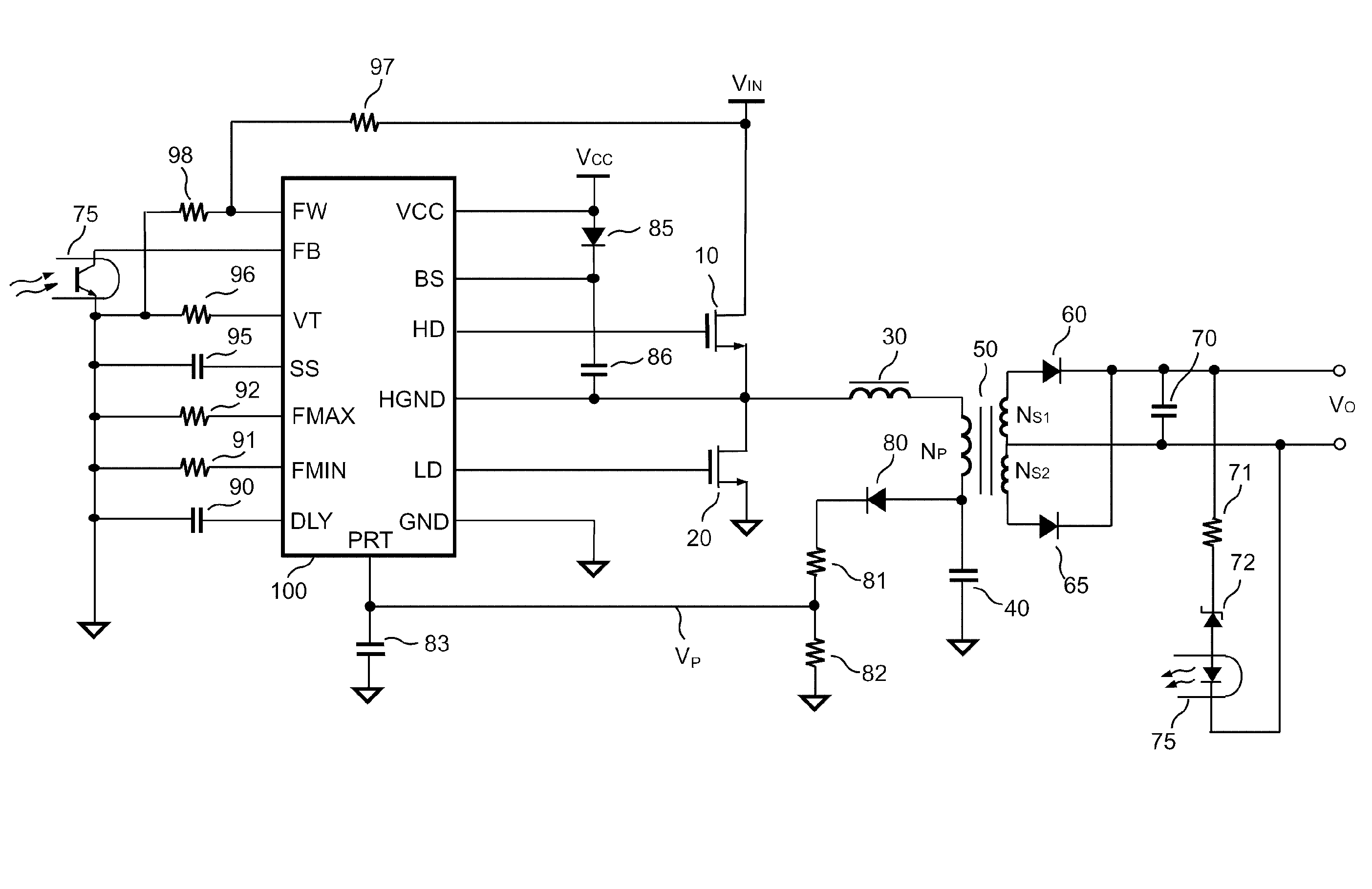
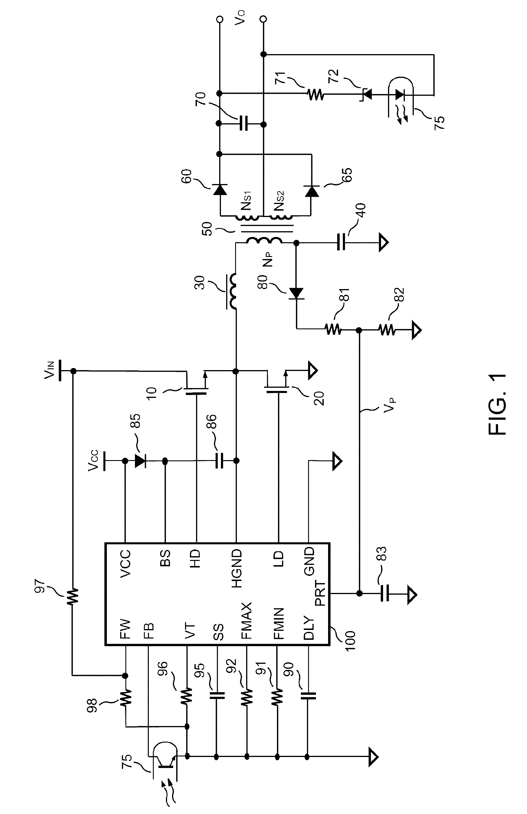
[0021]FIG. 1 shows a resonant power converter including a switching controller 100 to control power switches 10 and 20. The power switch 10 is connected to the input voltage VIN of the power converter. The power switch 20 is connected to the ground. Power switches 10 and 20 form a half bridge circuit to switch the primary winding NP of a transformer 50 through a series resonant circuit. An inductance device 30 and a capacitor 40 develop the resonant circuit. A maximum power is delivered to the secondary windings NS1, NS2 of the transformer 50 when the switching frequency of power switches 10, 20 is operated at the resonant frequency f0 of the resonant circuit.

[0022]f0=12⁢π⁢L30⁢×C40(1)

[0023]The second...


PUM


Abstract

An integrated control circuit for a resonant power converter includes a minimum-frequency programming circuit connected a first resistor to program a minimum switching frequency of the power converter. A feedback circuit is coupled to a feedback terminal to receive a feedback signal for generating an adjustment signal. A maximum-frequency programming circuit connects a second resistor to determine a maximum switching frequency in response to the adjustment signal. An oscillator is coupled to the minimum-frequency programming circuit and the maximum-frequency programming circuit to generate an oscillation signal for determining the switching frequency of the power converter. A feed-forward circuit is connected to a feed-forward terminal to receive a feed-forward signal represents the input voltage of the power converter. The switching frequency is increased in response to decrease of the feedback signal, and the switching frequency is increased in response to the increase of the feed-forward signal.

Description

BACKGROUND OF THE INVENTION[0001]1. Field of Invention[0002]The present invention relates to resonant power converters, and more particularly to the control circuit of the resonant power converter.[0003]2. Description of Related Art[0004]Power converters are used to convert an unregulated power source to a constant power source. A power converter normally includes a transformer having primary and secondary winding to provide the isolation. Switching devices connected in the primary winding control energy transferring from the primary winding to the secondary winding. The power converters operate at high frequencies allows a size and weight reduction. However, the switching losses, component stresses, and electric-magnetic-interference (EMI) are inherent problems. In the last decades, many resonant power converters have been proposed for high frequency power conversion to reduce the switching losses. Among them, the resonant switching techniques are described in following prior arts:...

Claims


Application Information

Patent Timeline
IPC IPC(8): H02M3/335
CPCH02M3/33523H02M3/3376Y02B70/1433Y02B70/10
Inventor YANG, TA-YUNGLIN, CHIEN-YUANSHIH, KUANG-CHIHWANG, WEI-TING
Owner SEMICON COMPONENTS IND LLC
Why Eureka
Try Eureka