
Integrated drilling dynamics system

a drilling dynamics and integrated technology, applied in the field of oil and gas production, can solve the problems of lateral vibration, high operating cost, and severe vibration in particular, and achieve the effects of reducing the risk of lateral vibration, reducing the safety of drilling equipment, and reducing the risk of drilling success

Active Publication Date: 2007-12-25
HALLIBURTON ENERGY SERVICES INC
View PDF8 Cites 24 Cited by
  • Summary
  • Abstract
  • Description
  • Claims
  • Application Information

AI Technical Summary

Benefits of technology

The present invention is a method and apparatus for accurately modeling the behavior of bottom-hole assemblies (BHAs) during drilling operations. It involves combining real-time modeling and downhole measurement-while-drilling (MWD) data. The invention includes a real-time BHA dynamics application for predicting critical rotary speeds and an MWD downhole vibration sensor for generating real-time downhole vibration data. The data is then integrated with mud logging and downhole data, and displayed in real-time using an integrated, closed-loop rigsite analysis system. This allows operators to modulate operational parameters in real-time to optimize drilling operations. Overall, the invention provides a more accurate understanding of BHA behavior and enables improved drilling performance.

Problems solved by technology

This is particularly so in the offshore environment, where operating costs are high, and in wells in which drilling problems are likely to occur.
Severe vibrations in particular have been shown to be harmful to downhole equipment used for drilling oil and gas wells.
Among them, lateral vibrations, particularly backward whirl, are commonly associated with drillstring fatique failure (wash-outs, twist-offs) excessive bit wear and measuring-while-drilling (“MWD”) tool failure.
A rotating body is unbalanced when its center of gravity does not coincide with its axis of rotation.
Due to such a crookedness or mass imbalance, centrifugal forces are generated while the unbalanced drillstring is rotating.
However, those of ordinary skill in the art will appreciate that vibration may not be reduced if the lower rotational speed results in a resonant condition in the assembly.
Under a resonant condition, the BHA has a tendency to vibrate laterally with continuously increasing amplitudes, resulting in severe vibration and causing drillstring and MWD failures.
However, the accuracy of predictions from such programs is often limited due to uncertainties in the input data and specified boundary conditions.
Common operational difficulties with conventional approaches to avoiding CRPMs are (i) complex BHA modeling and results; (ii) inaccurate modeling and results due to incorrect input data; and (iii) modeling results not being used in conjunction with real-time vibration data to optimize the drilling process.
That is to say, in the prior art is has not customarily been the case that dynamics analysis is carried out in an integrated, closed-loop manner, but instead occurs primarily or exclusively during the well-planning phase, such that there is limited opportunity for optimization of well operation.

Method used


Image

  • Integrated drilling dynamics system
  • Integrated drilling dynamics system
  • Integrated drilling dynamics system

Examples


Embodiment Construction

[0017]The disclosure that follows, in the interest of clarity, does not describe all features of actual implementations. It will be appreciated that in the development of any such actual implementation, as in any such project, numerous engineering and design decisions must be made to achieve the developers' specific goals and subgoals, which may vary from one implementation to another. Moreover, attention will necessarily be paid to proper engineering and programming practices for the environment in question. It will be appreciated that such a development effort might be complex and time-consuming, but would nevertheless be a routine undertaking for those of ordinary skill in the relevant field.

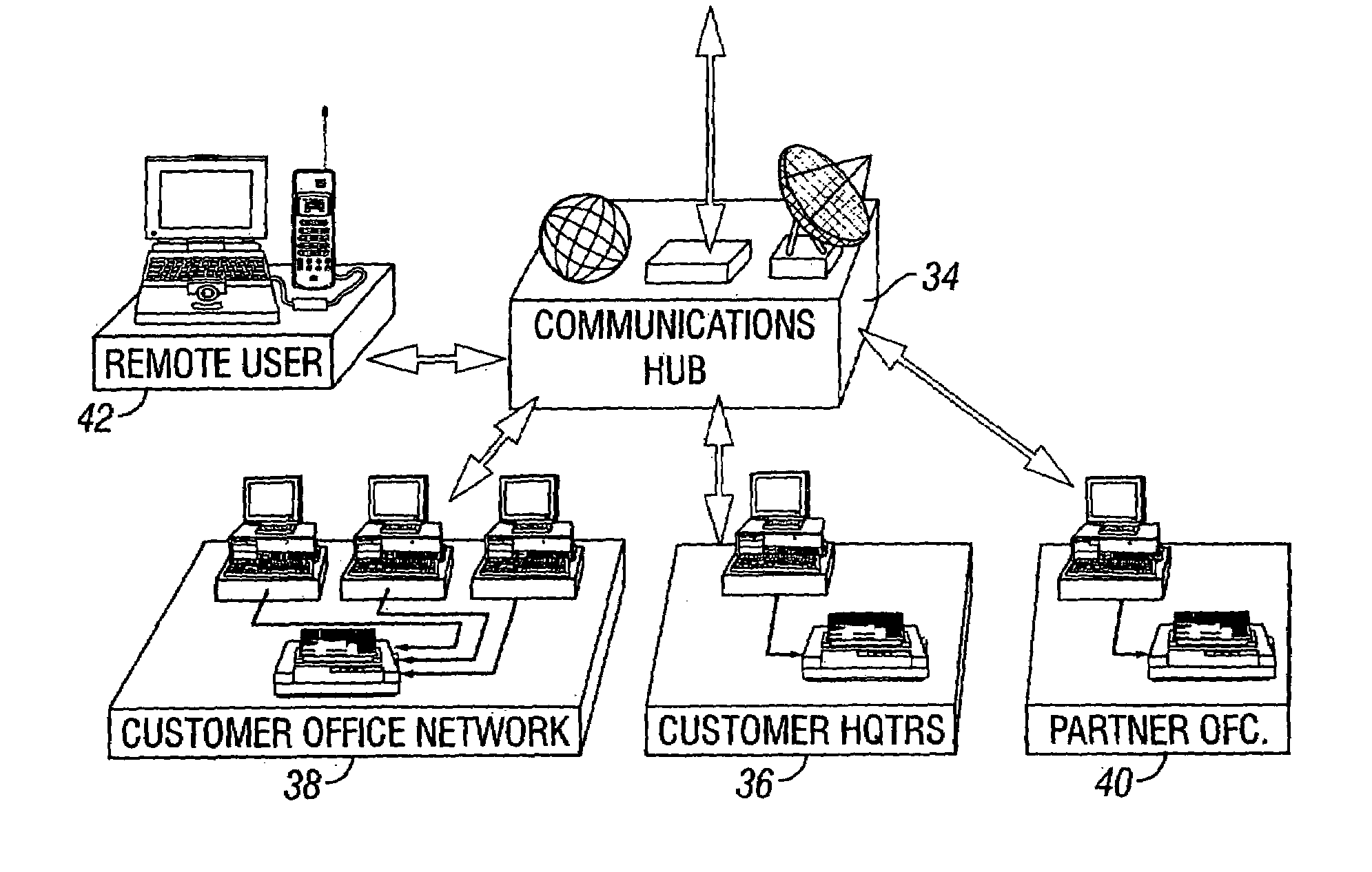
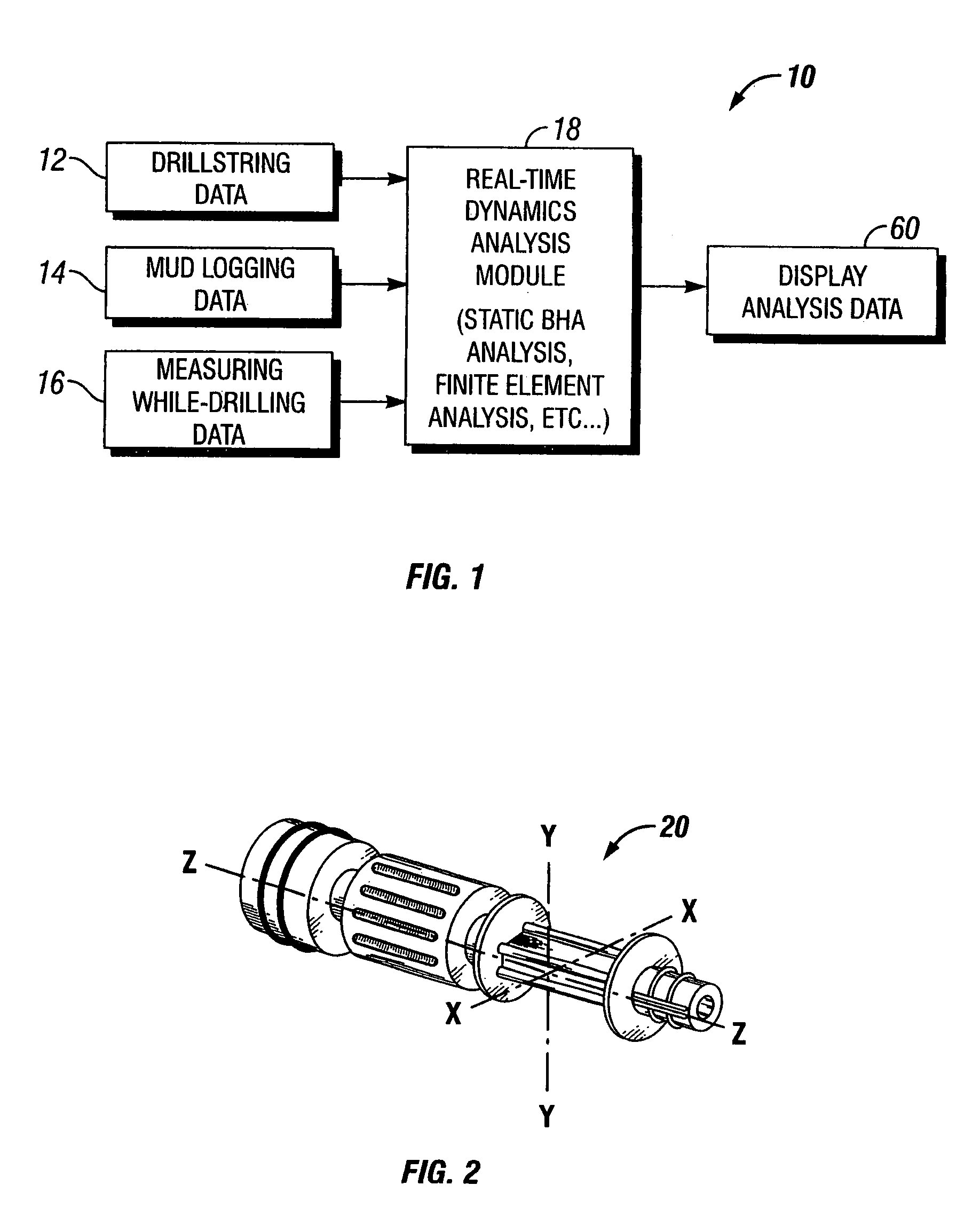
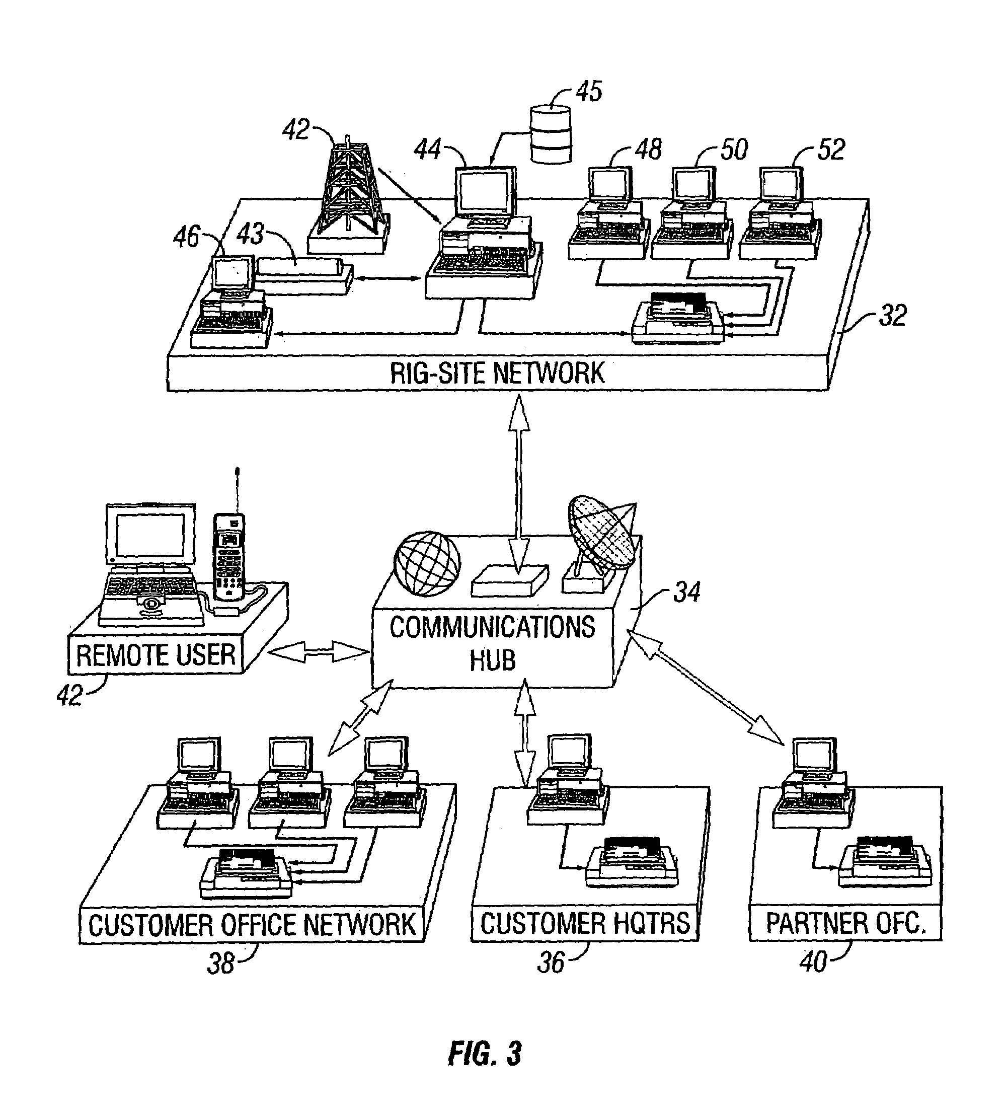
[0018]Referring to FIG. 1, there is shown a block diagram depicting the high-level functionality of an integrated drilling dynamics system 10 in accordance with one embodiment of the invention. As shown in FIG. 1, the present invention involves the collection and analysis of various operation...


PUM


Abstract

A method and apparatus for controlling a drilling operation involving the rotation of a bottom-hole assembly carried by a drillstring. In one embodiment, an integrated, closed-loop rigsite analysis system is provided for acquiring and analyzing real-time mud logging and downhole data, and displaying in real-time values of one or more operator-controllable parameters, along with dynamic critical values of at least one controllable operating parameter, thereby enabling an operator to modulate such parameter on a real-time basis to optimize operation. The integrated information is derived by intelligent combination of data into meaningful and useable information that can be displayed in an informative manner.

Description

RELATED APPLICATION[0001]This application claims the priority of prior provisional application Ser. No. 60 / 440,819, filed on Jan. 17, 2003, which application is hereby incorporated by reference herein in its entirety.FIELD OF THE INVENTION[0002]The present invention relates generally to the field of oil and gas production, and more particularly relates to oil and gas well drilling equipment.BACKGROUND OF THE INVENTION[0003]Drilling costs are a critical factor in determining the financial returns from an oil and gas investment. This is particularly so in the offshore environment, where operating costs are high, and in wells in which drilling problems are likely to occur. Severe vibrations in particular have been shown to be harmful to downhole equipment used for drilling oil and gas wells. Among them, lateral vibrations, particularly backward whirl, are commonly associated with drillstring fatique failure (wash-outs, twist-offs) excessive bit wear and measuring-while-drilling (“MWD”)...

Claims


Application Information

Patent Timeline
Patent Type & Authority Patents(United States)
IPC IPC(8): G06F19/00G01V9/00E21BE21B44/00E21B47/00G01V1/40
CPCE21B44/00G01V1/40
Inventor CHEN, CHENKANG DAVIDSMITH, MARKLAPIERRE, SCOTT
Owner HALLIBURTON ENERGY SERVICES INC
Learn More