Method of power conversion and apparatus which achieves high power factor correction using ripple current mode control

a ripple current mode and power conversion technology, applied in the direction of electric variable regulation, process and machine control, instruments, etc., can solve the problems of difficult configuration, harmonic distortion of ac line voltage, polluted ac line voltage, etc., to achieve high power factor, reduce peak current levels, and increase signal gain for current sensing

Active Publication Date: 2008-01-01
INTEGRATED CIRCUIT DESIGN
View PDF8 Cites 11 Cited by
  • Summary
  • Abstract
  • Description
  • Claims
  • Application Information

AI Technical Summary

Benefits of technology

[0017]The present invention relates to power conversion employing a novel method of control that will hereafter be referred to as ripple current mode control. Ripple current mode control is a control method of that achieves a high power factor without the need to monitor the input AC source voltage or current. The AC input current in inferred from two charge current samples. This approach has great advantages over conventional approaches to power factor correction because the signal gain for current sensing can be high without wasting power over the entire switching interval. Also, ripple current mode control is operable in continuous current mode. Continuous current mode is desirable because the peak currents levels can be minimized for a given average current, which alleviates unwanted component stresses. Continuous current mode lowers the amplitude of switching frequency harmonics worsened by high inductor ripple current levels that are typical of discontinuous current mode approaches. The ripple current mode control calculations can be implemented in a digital signal processor, micro-controller, custom digital hardware, or by standard analog computational elements, which broadens the applications where ripple current mode control is applicable.

Problems solved by technology

These unwanted harmonics distort the AC line voltage due to source impedance, and pollute the AC line voltage.
The result is an implementation that is difficult to configure, and is not suitable of a modular design approach.

Method used


Image

  • Method of power conversion and apparatus which achieves high power factor correction using ripple current mode control
  • Method of power conversion and apparatus which achieves high power factor correction using ripple current mode control
  • Method of power conversion and apparatus which achieves high power factor correction using ripple current mode control

Examples


Embodiment Construction

Definitions

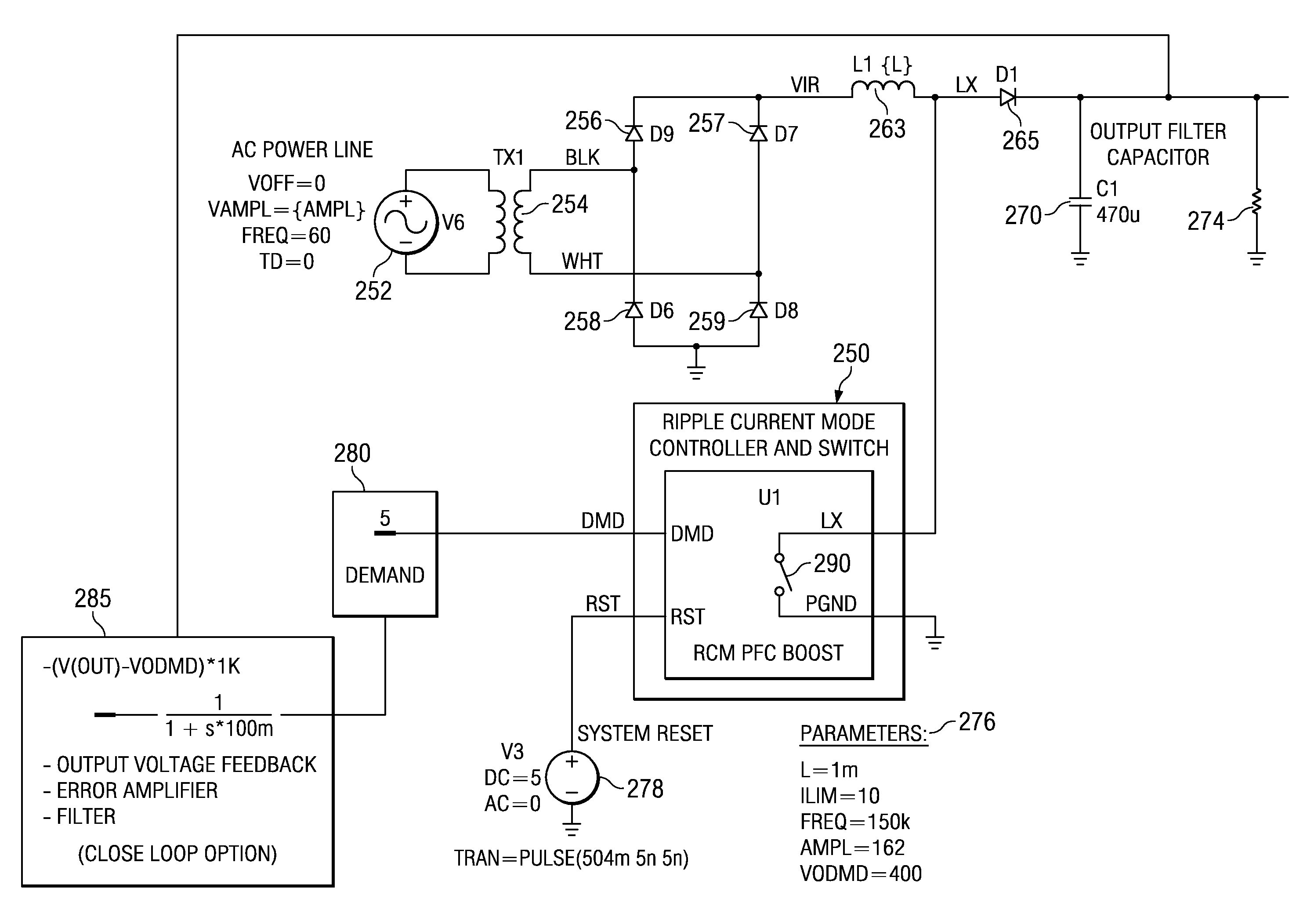
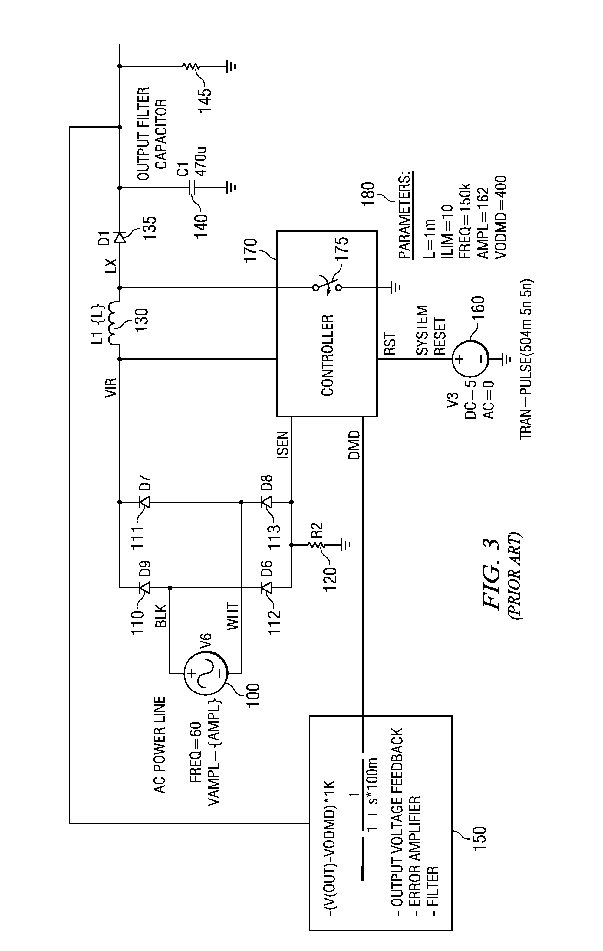
[0051]Ripple Current Mode Control is a method of power conversion, which achieves a high power factor using an AC voltage source and a demand signal to produce a power source for a load.

[0052]The Switching Cycle is the duration between to consecutive charge cycles. The switching cycle is equal to the period of the operating frequency of the converter. Thus, if the operating frequency to the converter is 100 k Hz, the switching cycle if 10 microseconds long

[0053]The Duty Cycle (D) is the ratio of the charge duration relative to the switching cycle duration.

[0054]The Rectified AC source is approximately equal to the absolute value of the AC voltage source.

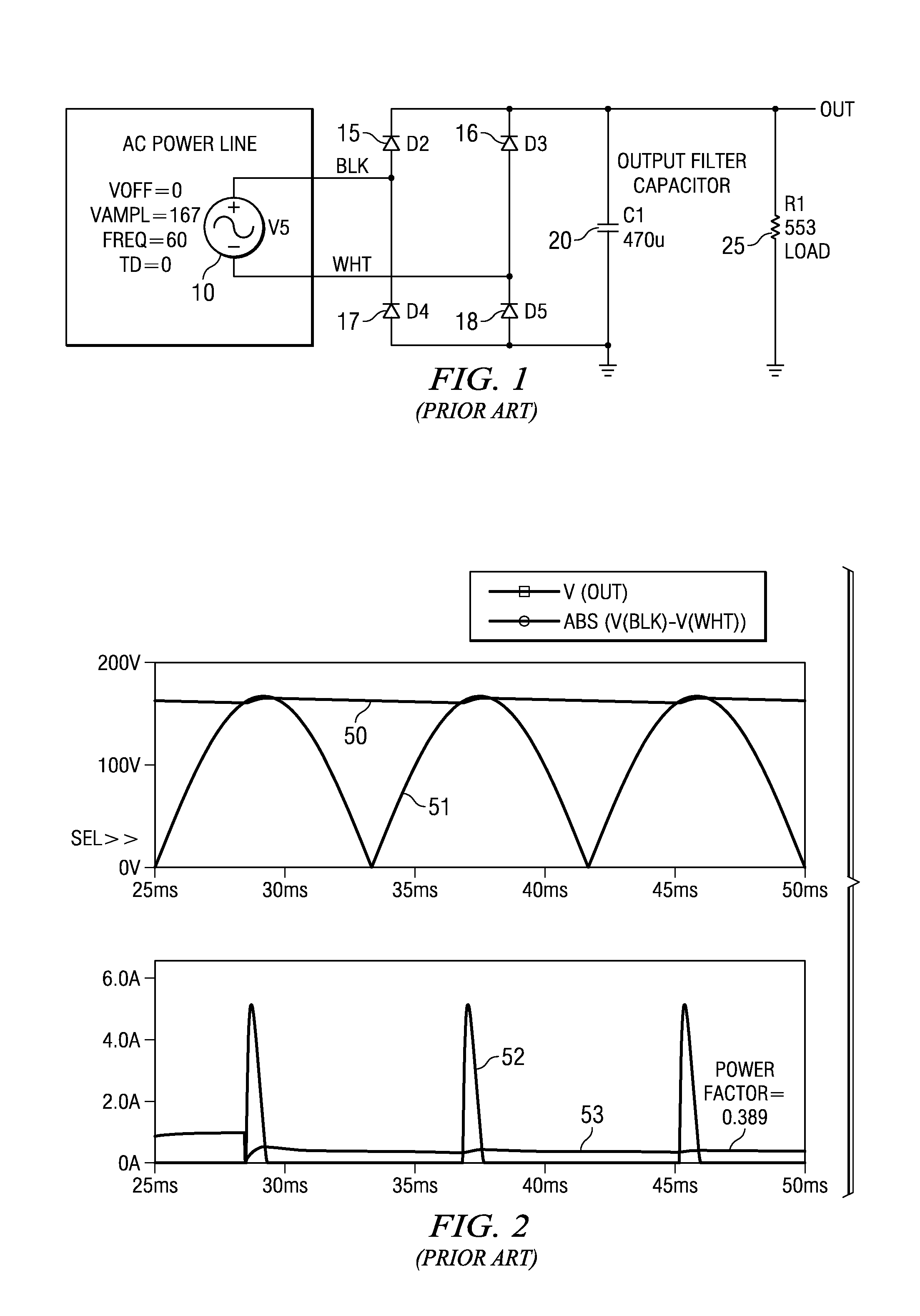
[0055]The Power Factor is the ratio of real power (kilowatts) to apparent power kilovolt-ampere for any given load and time.

[0056]Power Factor Correction is a method of increasing the power factor of a system.

[0057]The Switching Frequency is the operating frequency of the power converter.

[0058]The Switching Period is the d...


PUM


Abstract

A ripple current mode power converter comprised of a magnetic energy storage element, and a method of determining magnetic storage element charge duration based on periodic magnetic storage element current samples. In the preferred embodiment a controller processes a magnetic storage element ripple current, and average sampled current, to achieve high power factor forgoing the need to sense the AC signal current and voltage levels. The controller element periodically calculates the magnetic storage element charge duration to control the state of the switch element to maintain the AC input current proportional to the AC input voltage.

Description

FIELD OF THE INVENTION[0001]The present invention relates to power factor correction, including power factor corrected switch based power converters.BACKGROUND OF THE INVENTION[0002]This invention relates generally to the field of power conversion, and more specifically to a method of power conversion and apparatus which achieves high power factor correction using ripple current mode control.[0003]Electronic equipment and specifically electronic products that rectify and filter the AC line pollute the AC power line with unwanted line current harmonics. These harmonics do not contribute to the transfer of power from the power source to various loads in a power system, which wastes energy in transfer losses due to wire resistance. Unwanted line current harmonics also reduce the useful life of induction motors and transformers, and lead to higher current ratings for protection devices such as fuses or circuit breakers. These higher current ratings lead to costly, larger gauge system wi...

Claims


Application Information

Patent Timeline
Patent Type & Authority Patents(United States)
IPC IPC(8): G05F1/10G05F1/652
CPCG05F1/70H02M1/4225Y02B70/126Y02B70/10
Inventor COLEMAN, EDWARD PAUL
Owner INTEGRATED CIRCUIT DESIGN
Why Eureka
Try Eureka