
Method and apparatus for absorbing thermal energy

Active Publication Date: 2008-01-08
RINI TECH
View PDF16 Cites 77 Cited by
  • Summary
  • Abstract
  • Description
  • Claims
  • Application Information

AI Technical Summary

Benefits of technology

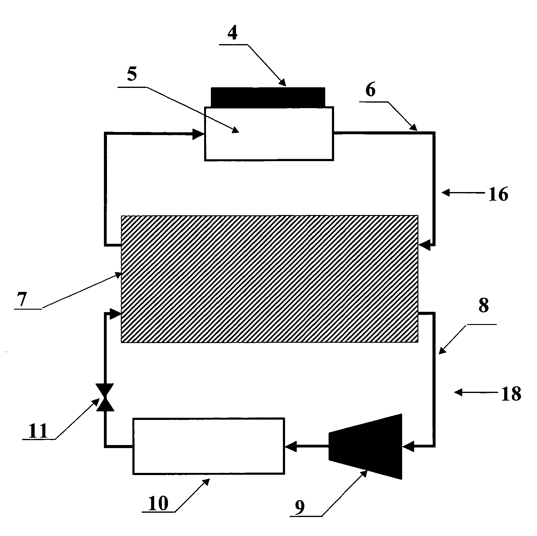
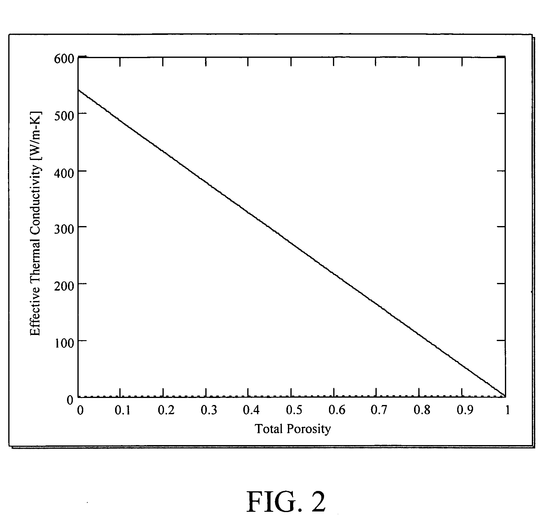
[0006]The subject invention pertains to a method and apparatus for storing thermal energy. The subject invention also relates to a method and apparatus for absorbing thermal energy from a heat source. The subject invention also relates to a method and apparatus for enhancing the thermal performance of a thermal energy storage device that absorbs thermal energy from a heat source. The subject invention uses a high thermal conductivity host material to house a lower thermal conductivity phase change material, in order to achieve a thermal energy absorber that has a high effective thermal conductivity. In a specific embodiment, the high thermal conductivity host material has have voids within the structure that can be filled by the phase change material. The increased surface area of phase change material in thermal contact with the host material per volume of phase change material allows the thermal energy to be stored or released quickly, because of the enhanced effective thermal conductivity. The quick storage of thermal energy can enable the subject device to be used to cool electronic devices with very small temperature increases in the electronic device that is being cooled.
[0007]Advantageously, the high conductivity host material can rapidly transfer the heat to the thermal energy storage system throughout a portion of, or the entirety of, the volume of the phase change material. The high conductivity host material of the subject invention conducts the thermal energy through the host material and into the phase change material over a large surface area of thermal contact between the host material and the phase change material. This feature can produce a very high rate of heat absorption.

Problems solved by technology

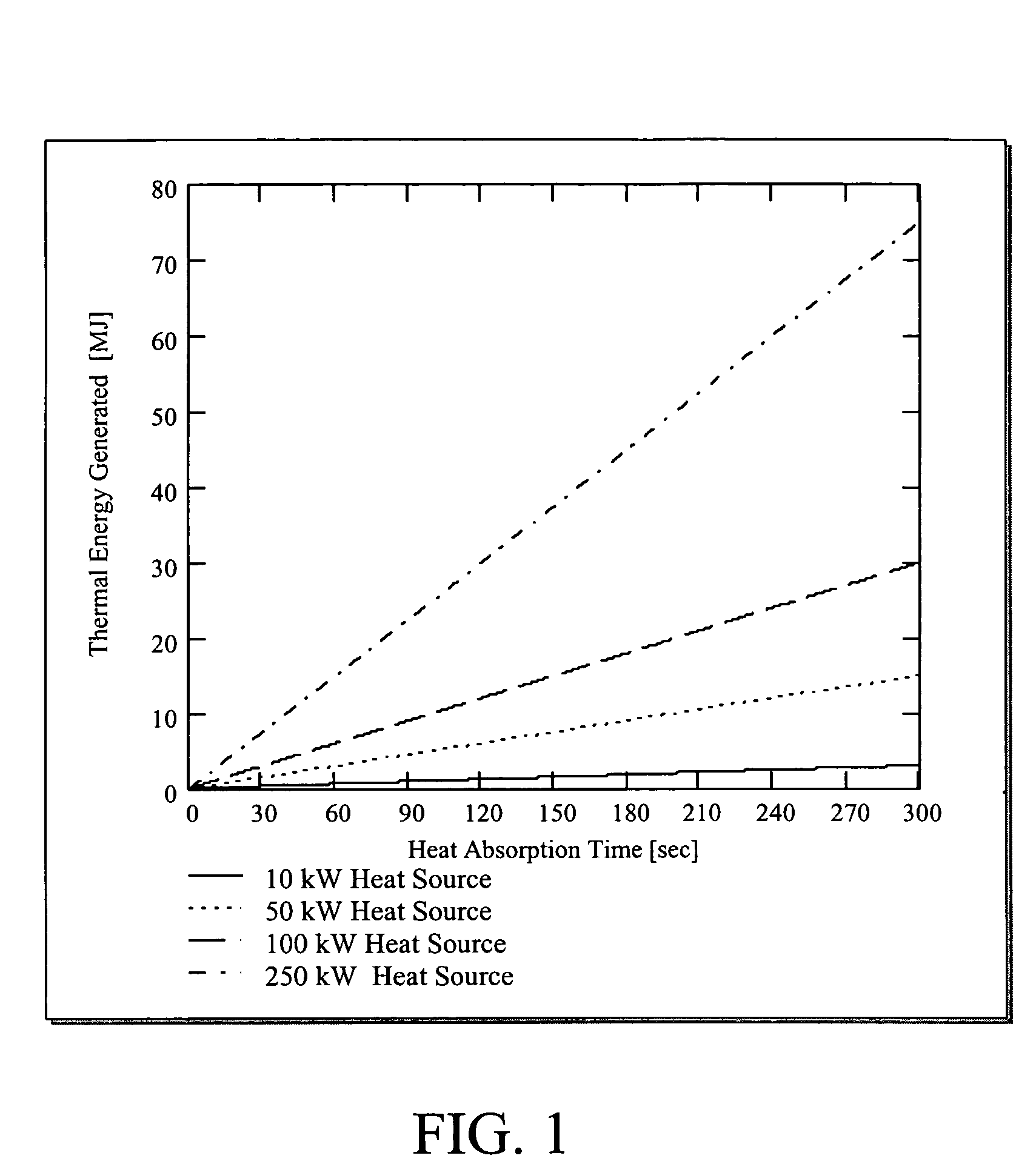
To remove over 900 kW using a refrigeration cycle in real time would require an extremely large refrigeration unit and would not be practical for most applications.

Method used


Image

  • Method and apparatus for absorbing thermal energy
  • Method and apparatus for absorbing thermal energy
  • Method and apparatus for absorbing thermal energy

Examples


Embodiment Construction

[0021]The subject invention pertains to a method and apparatus for storing thermal energy. In a specific embodiment, the subject thermal energy storage apparatus can function as a heat absorber in a cooling system. In a further specific embodiment, a cooling system can incorporate a cooling cycle that utilizes thermal energy storage and has two coolant loops. The primary cooling loop acquires the waste heat from a heat source, such as an electronic device, by heat transfer to the primary coolant via, for example, a sensible heat process (where sensible heat is heat absorbed or transmitted by a substance during a change in temperature which is not accompanied by a change of state) or by evaporating the primary coolant through a latent heat phase change process.

[0022]The waste heat absorbed by the primary coolant is transferred to the host material of the heat absorber. In a specific embodiment, the waste heat is transferred to the host material of the heat absorber by tubing that can...


PUM


Abstract

The subject invention pertains to a method and apparatus for storing thermal energy. The subject thermal energy storage apparatus can function as a heat absorber in a cooling system. A cooling system can incorporate a cooling cycle that utilizes thermal energy storage and has two coolant loops. The primary cooling loop acquires the waste heat from a heat source, such as an electronic device, by heat transfer to the primary coolant via, for example, a sensible heat process (where sensible heat is heat absorbed or transmitted by a substance during a change in temperature which is not accompanied by a change of state) or by evaporating the primary coolant through a latent heat phase change process. The waste heat absorbed by the primary coolant is transferred to the host material of the heat absorber. The subject invention uses a high thermal conductivity host material to house a lower thermal conductivity phase change material, in order to achieve a thermal energy absorber that has a high effective thermal conductivity. In a specific embodiment, the high thermal conductivity host material has have voids within the structure that can be filled by the phase change material. The increased surface area of phase change material in thermal contact with the host material per volume of phase change material allows the thermal energy to be stored or released quickly, because of the enhanced effective thermal conductivity.

Description

CROSS-REFERENCE TO RELATED APPLICATION(S)[0001]The present application claims benefit of U.S. Provisional Application Ser. No. 60 / 539,153, filed Jan. 26, 2004, which is hereby incorporated by reference herein in its entirety, including any figures, tables, or drawings.FIELD OF THE INVENTION[0002]The subject invention pertains to a method an apparatus for storing thermal energy. The subject invention also relates to a method and apparatus for absorbing thermal energy from a heat source. In a specific embodiment, the subject thermal energy storage apparatus can function as a heat absorber in a cooling system.BACKGROUND OF THE INVENTION[0003]Many heat absorption and / or heat storage applications have high heat loads, require precise temperature control, and / or have limited heat rejection options. Such applications include, but are not limited to, cooling microelectronics such as computer processors, cooling power conditioning equipment for prime power generation, cooling high-power lase...

Claims


Application Information

Patent Timeline
IPC IPC(8): F28D17/04
CPCF28D20/023Y02E60/145Y10S165/902Y02E60/14
Inventor RINI, DANIEL P.CHOW, LOUIS
Owner RINI TECH
Learn More