Gastric bypass prosthesis

a gastric bypass and prosthesis technology, applied in the field of morbid obesity surgical treatment, can solve the problems of band slipping out of position, affecting the effect of the procedure, so as to reduce the incidence of reflux, reduce the amount of food intake of patients, and increase the opening pressure

Inactive Publication Date: 2008-01-08
EGAN THOMAS +1
View PDF20 Cites 243 Cited by
  • Summary
  • Abstract
  • Description
  • Claims
  • Application Information

AI Technical Summary

Benefits of technology

[0025]The forgoing objects are met in a new device and method for the treatment of morbid obesity. This new device and method achieve the restrictive aspect of vertical banded gastroplasty and roux-en-y gastric bypass through formation of a stomach pouch substantially smaller than the natural stomach. This is achieved through installation of an annular element, preferably a funnel-like shaped or conical-shaped element, which is circumferentially attached to the stomach wall dividing the stomach into two regions: the esophagus-end chamber and the pylorus-end chamber. In a preferred embodiment, the conical-shaped element is equipped with a reinforced flange extending from a proximal end of the conical-shaped element. The flange is capable of accepting sutures or staples. In one preferred embodiment, the flange is turned inward to accept the anvil element of a circular anastomotic stapler. In a preferred embodiment, the volume of the esophagus-end chamber (pouch) between the lower esophageal sphincter and the conical element is equivalent to the pouch formed in standard surgical practice for roux-en-y gastric bypass: about 30 ml to 70 ml, thus limiting the amount of food intake of a patient.
[0026]The conical-shaped element includes an interior hollow region having an opening at its distal end for passage of swallowed food into the remainder of the gastrointestinal tract (GI tract). In one embodiment, this opening is a substantially circular orifice with a diameter equivalent to the target diameter of the anastomotic stoma formed surgically in gastric bypass surgery, approximately 8 to 12 mm. In a preferred embodiment, this opening includes a valve assembly for closing the opening to prevent spontaneous passage of swallowed food or liquid until the natural digestive regulation and coordination processes trigger movement and contraction of the stomach wall in the esophagus-end chamber. The controlling of the opening is preferably accomplished by the presence of a valve that requires positive pressure differential between the proximal side of the valve and the distal side of the valve to open (for the purpose of this description, proximal shall mean closer to the mouth end of the digestive tract and distal shall mean closer to the colon end when the device is in use). Opening pressure for this stoma valve should be greater than the pressure caused by gravity on a standing column of food within the pouch (1 to 5 mmHg) and less than the continent manometric pressure of-the lower esophageal sphincter (about 15 to 30 mmHg in healthy humans.) In one preferred embodiment, this valve has a higher opening pressure in the retrograde direction than in the forward direction to reduce the incidence of reflux into the esophagus. In another preferred embodiment, the stoma valve employs a valve with hysteresis such that the valve opens fully at an initial cracking pressure and closes fully at a closing pressure lower than the cracking pressure, thereby offering more complete emptying of the pouch with smaller stomach wall contraction pressures. In another preferred embodiment, the pouch stoma valve communicates with the pyloric sphincter such that the stoma valve opens upon relaxation of the pyloric sphincter muscle and closes in sync with pyloric sphincter muscle pressure.
[0027]In another preferred embodiment, further elements are added to provide a malabsorptive aspect to the device. In one embodiment, the malabsorptive aspect is achieved by providing an elongated flexible tube extending from the distal end of the conical-shaped element to a distal end. The elongated flexible tube has a length so that the tube passes the pylorus of the patient and the distal end is positioned in the intestine when the device is in use. The elongated flexible tube defines an inner central lumen which establishes communication between the distal stoma orifice or the valve of the conical-shaped element and the intestines distal to the pylorus, but not in communication with the pylorus-end chamber between the distal side of the conical-shaped element and the pyloric sphincter, thereby isolating this otherwise absorptive stomach region from contact with food. In one preferred embodiment, the tube is made of a flexible material such that the natural muscular movement of the stomach creates a pumping action to the tube to assist in transporting food through the lumen. In one preferred embodiment, the portion of the lumen transiting the pyloric sphincter has sufficient diametric rigidity to resist collapse from pyloric sphincter pressure. In other embodiments, particularly the embodiment without a stoma valve at the distal end of the conical-shaped element, the region transiting the pyloric sphincter is sufficiently pliable to allow the tube to collapse and the lumen to be closed under pyloric sphincter pressure.
[0028]In one embodiment, the diameter of the flexible tube is sized to provide a space between the outer surface of the tube and the circumference of the pylorus when the sphincter is in a relaxed state, to allow passage of any excess stomach acid that may have accumulated in the pylorus-end chamber. In other embodiments, passageways are provided on the outer surface of the flexible tube, for example, grooves defined on the outer surface of the tube, to allow passage of the stomach acid when the pyloric sphincter is in the closed state. In another preferred embodiment, passageways are provided to allow stomach acid to pass one-way from the pylorus-end chamber into the inside of the lumen to assist in breakdown of food within the lumen.
[0029]In one preferred embodiment, the elongated flexible tube extends beyond the pylorus and ends in the upper duodenum. In another preferred embodiment, the elongated flexible tube transits a portion of the duodenum, which portion has a length equivalent to the length of the portion of the duodenum bypassed in standard practice of a roux-en-y gastric bypass surgery (approximately 50 to 200 cm), thereby rendering this portion of the intestine malabsorptive. In a further preferred embodiment, the elongated flexible tube includes at least a portion that is collapsible under peristaltic pressure from the stomach or the intestinal wall, thereby allowing food to be transported through the lumen by means of stomach or intestinal peristalsis. In another preferred embodiment, the collapsible portion starts from the proximal end of the duodenum to the distal end of the tube. In one preferred embodiment, the portion of the tube in the duodenum region is constructed such that it is in a naturally collapsed state, such as a flattened tube, with no external pressure required to compress the tube closed. In another preferred embodiment, the tube is constructed such that the inner central lumen is in a naturally open state, such as a round tube, such that external pressure is required to pinch the lumen closed and the lumen returns to the open state when external pressure is removed. In another preferred embodiment, a portion of the tube which is disposed in the peristaltic portion of the duodenum when the device is in use is made of an elastic material. The portion of the tube may be compressed by the peristalsis of the duodenum and the elastic wall of the tube forces tube to return to its naturally open state when the pressure from the duodenum peristalsis is removed, thereby creating a negative pressure within the lumen to assist in propulsion of food in the distal direction and to assist in sucking stomach acid into the inside of the lumen through the one-way acid valve, if provided.
[0031]Preparation: An endoscopic suturing device such as the C. R. BARD ENDOCINCH™, or other endoscopic suturing device known to the art, will be used to place a plurality of sutures (10 to 12 sutures in a preferred embodiment) in the gastric cardiac region in a ring approximately 3 cm distal to the gastroesophageal junction. The sutures will be 2 m long polypropylene monofilament placed in a mattress configuration with a felt pledget. The suture tails, in pairs, will be passed through the circumference of the gastric bypass prosthesis (GBP) attachment ring flange using a free needle. A system of cut-away tubes (i.e. drinking straws) may be used to organize the strands and prevent suture pair entanglement.

Problems solved by technology

In both types of procedure, the size of the stoma is critical to the success of the procedure; too much constriction prevents food from passing, too little allows food to pass freely, defeating the purpose of the procedure.
Limitations and problems of vertical banded gastroplasty include the need for irreversible stomach stapling in the case of the Mason procedure and a tendency for the band to slip out of position in the European and Kuzmak procedures.
Dumping occurs when the patient eats refined sugar following gastric bypass, this causes symptoms of rapid heartbeat, nausea, tremor and fainting, sometimes followed by diarrhea.
Limitations and problems of Roux-en-y gastric bypass include the extremely invasive, irreversible nature of reconfiguring the digestive system.
Also, the anastomotic connections of the procedure are prone to stomal stenosis and obstruction.
Prior inventions of devices for the treatment of obesity have failed to provide, in combination, the three elements of Roux-en-y gastric bypass that made the procedure so successful: restriction of food intake by drastically reduced stomach volume, malabsorption from isolation of the majority of the stomach and part of the intestines from the digestive process, and the negative reinforcement of dumping syndrome that results when sugars and fat reach the jejunum without prior partial digestion.

Method used


Image

  • Gastric bypass prosthesis
  • Gastric bypass prosthesis
  • Gastric bypass prosthesis

Examples


Embodiment Construction

[0065]For the purposes of promoting an understanding of the present invention, reference will now be made to the embodiments illustrated in the drawings and specific language will be used to describe the same.

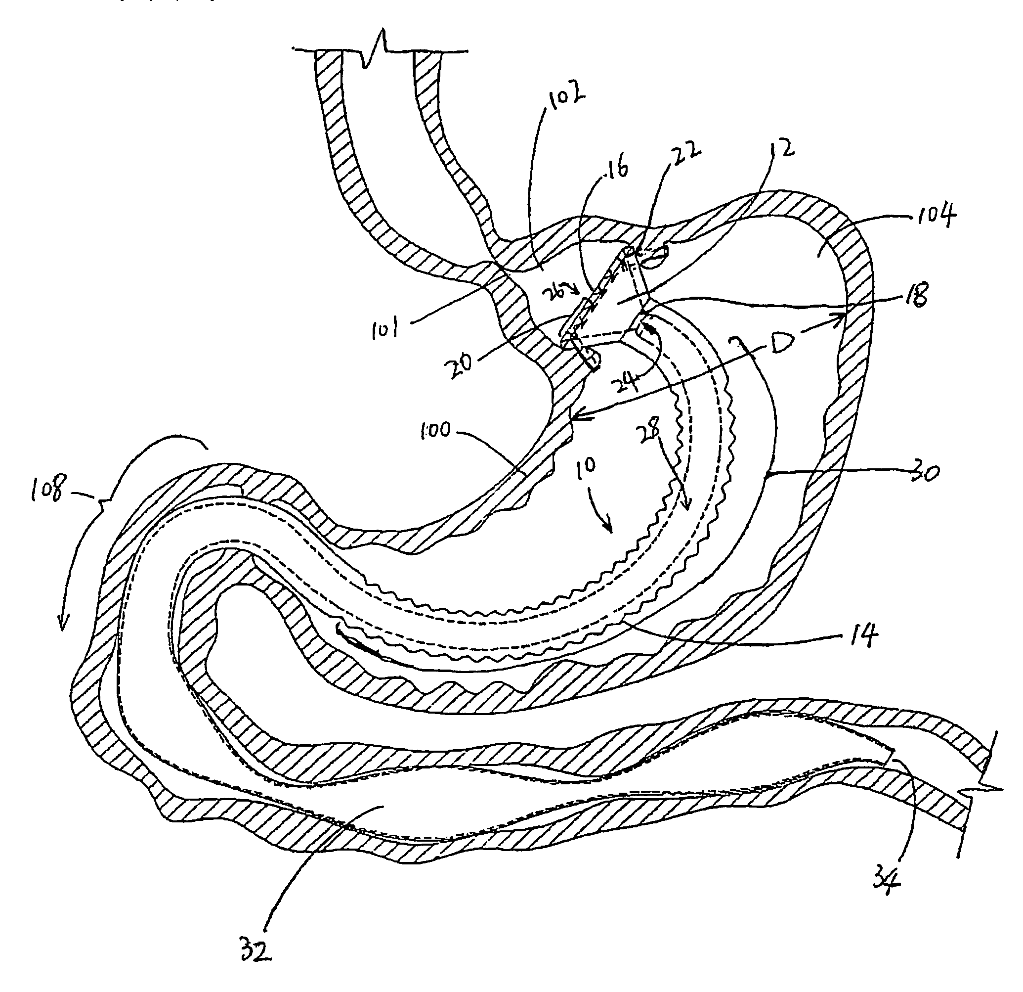
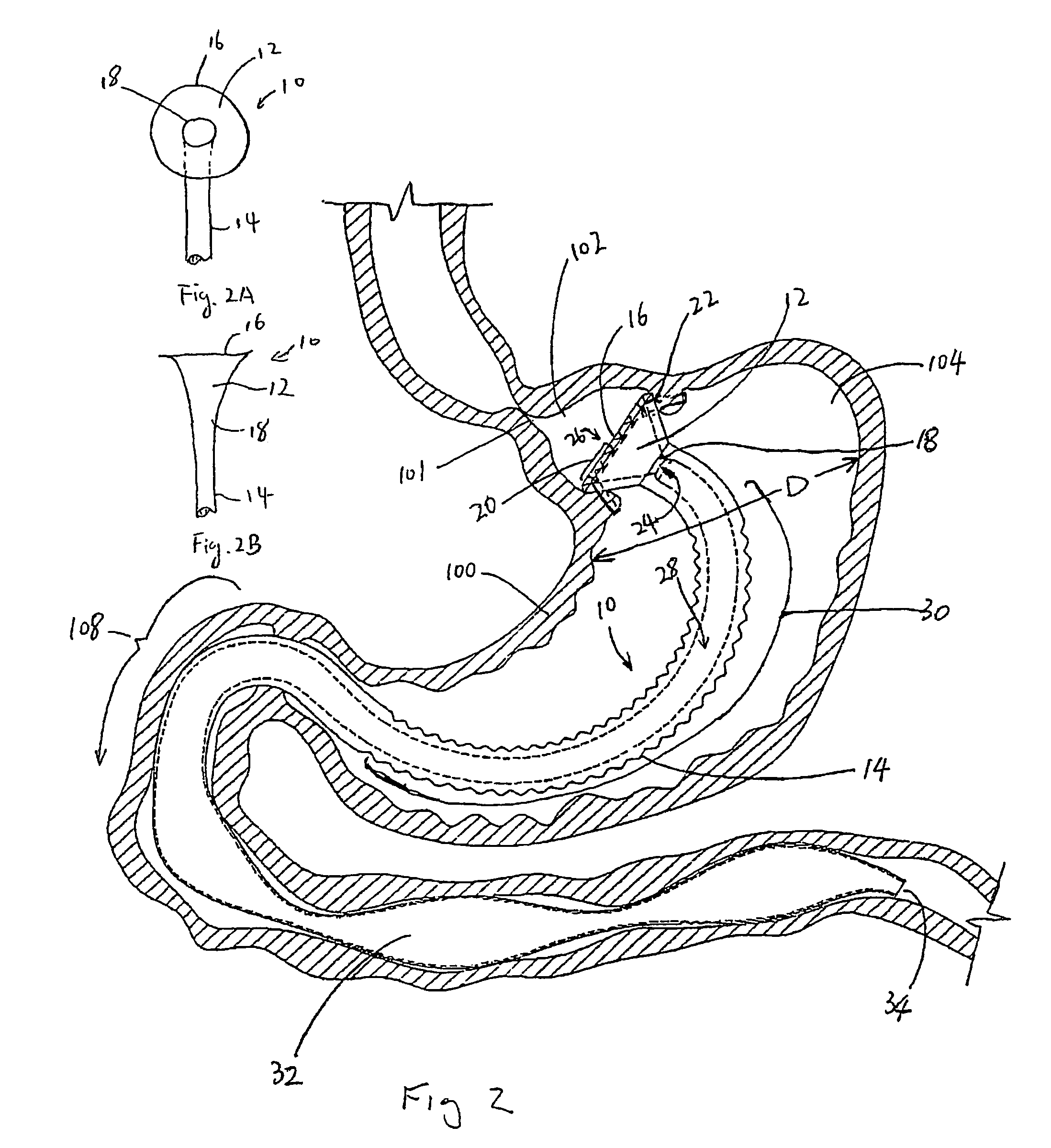
[0066]FIG. 2 shows a preferred embodiment of a gastric bypass prosthesis in accordance with the present invention. As shown in FIG. 2, the gastric bypass prosthesis 10, which is disposed in a stomach 100, includes a substantially annular element 12 and an elongated tubular element 14. In other preferred embodiments, as shown in FIGS. 2, 2A, and 2B, the annular element 12 may be flat (FIG. 2A), substantially conical-shaped, funnel-shaped, or trumpet-shaped (FIG. 2B). The element 12 also can be constructed with other shapes suitable for attaching to the stomach lining. The element 12 is preferably made of a flexible material, but also can be made of rigid or semi-rigid materials. In one preferred embodiment, the annular element 12 may be flat-shaped and made of a flexible materia...


PUM

PropertyMeasurementUnit
volumeaaaaaaaaaa
diameteraaaaaaaaaa
lengthaaaaaaaaaa

Abstract

A device (10) for treatment of obesity of a patient comprises an annular element (12) having a relatively large outer boundary and a relatively small inner boundary, and an elongated flexible tube (14) extending from the relatively small inner boundary of the annular element to a distal end. The relatively large outer boundary is adapted to be attached to an inner wall of a stomach (100) of a patient, such that the annular element divides the stomach (100) into two chambers, an esophagus-end chamber close to an esophagus of the patient, and a pylorus-end chamber close to a pylorus of the patient. The invention also provides a method for treatment of obesity of a patient which includes inserting an annular element having a relatively large outer boundary and a relatively small inner boundary into a stomach of the patient, and attaching the relatively large outer boundary of the annular element to an inner circumference of the stomach of the patient.

Description

FIELD OF THE INVENTION[0001]The present invention relates to devices and methods for surgical treatment of morbid obesity, and in particular to devices and methods for gastric bypass surgery.BACKGROUND OF THE INVENTION[0002]Surgery for obesity accomplishes weight loss through restriction of food intake by a restrictive procedure, malabsorption of food by a malabsorptive procedure, or a combination of both restrictive and malabsorptive procedures.[0003]The history of gastric bypass surgery for the treatment of morbid obesity is summarized in The Story of Surgery for Obesity, compiled by Alex MacGregor, MD. Many arrangements of gastric bypass have been tried in prior art. Based on success rate and a low complication rate, two procedures have risen to dominance in the field: vertical banded gastroplasty and Roux-en-y gastric bypass.[0004]Vertical banded gastroplasty was developed by Dr. Edward E. Mason, Professor of Surgery at the University of Iowa in 1982. This technique, and its man...

Claims


Application Information

Patent Timeline
Patent Type & Authority Patents(United States)
IPC IPC(8): A61F2/04A61B17/00A61L31/00A61B17/04A61B17/068A61B17/115A61F5/00
CPCA61F2/04A61F5/0076A61B17/00491A61B17/0469A61B17/068A61B17/115
Inventor EGAN, THOMAS D.
Owner EGAN THOMAS
Why Eureka
Try Eureka