Method and apparatus for multi-phase DC-DC converters using coupled inductors in discontinuous conduction mode

a technology of coupled inductors and converters, which is applied in the direction of dc-dc conversion, power conversion systems, instruments, etc., can solve problems such as power losses, and achieve the effect of high efficiency

Active Publication Date: 2008-01-08
VOLTERRA SEMICONDUCTOR
View PDF8 Cites 105 Cited by
  • Summary
  • Abstract
  • Description
  • Claims
  • Application Information

AI Technical Summary

Benefits of technology

[0010]A multi-phase, coupled-inductor, DC-DC voltage converter operates in discontinuous conduction mode (DCM) when the system is operated at low output power levels. The converter achieves high efficiency in the described DCM operation at low output power levels.

Problems solved by technology

Therefore, there are power losses, such as those due to resistive loss in converter switches and inductor windings, and those due to charging and discharging the parasitic capacitors of the switches, that are present even when the converter operates at low load.
Therefore, with CCM operation, the switching loss and the AC current related loss do not scale down with decreasing load current and they may become a significant part of the total power absorbed by the converter when the load current is small.

Method used


Image

  • Method and apparatus for multi-phase DC-DC converters using coupled inductors in discontinuous conduction mode
  • Method and apparatus for multi-phase DC-DC converters using coupled inductors in discontinuous conduction mode
  • Method and apparatus for multi-phase DC-DC converters using coupled inductors in discontinuous conduction mode

Examples


Embodiment Construction

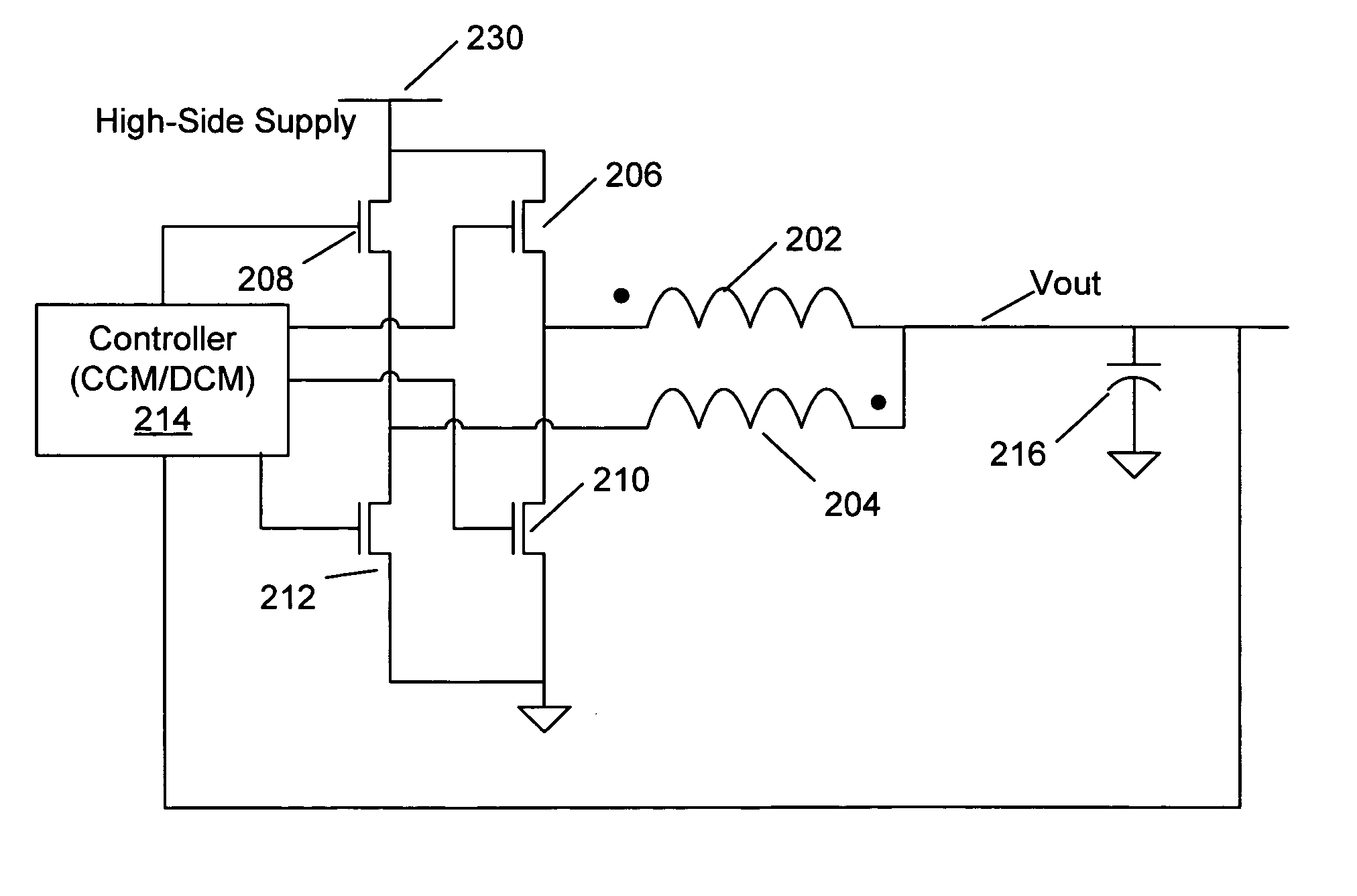
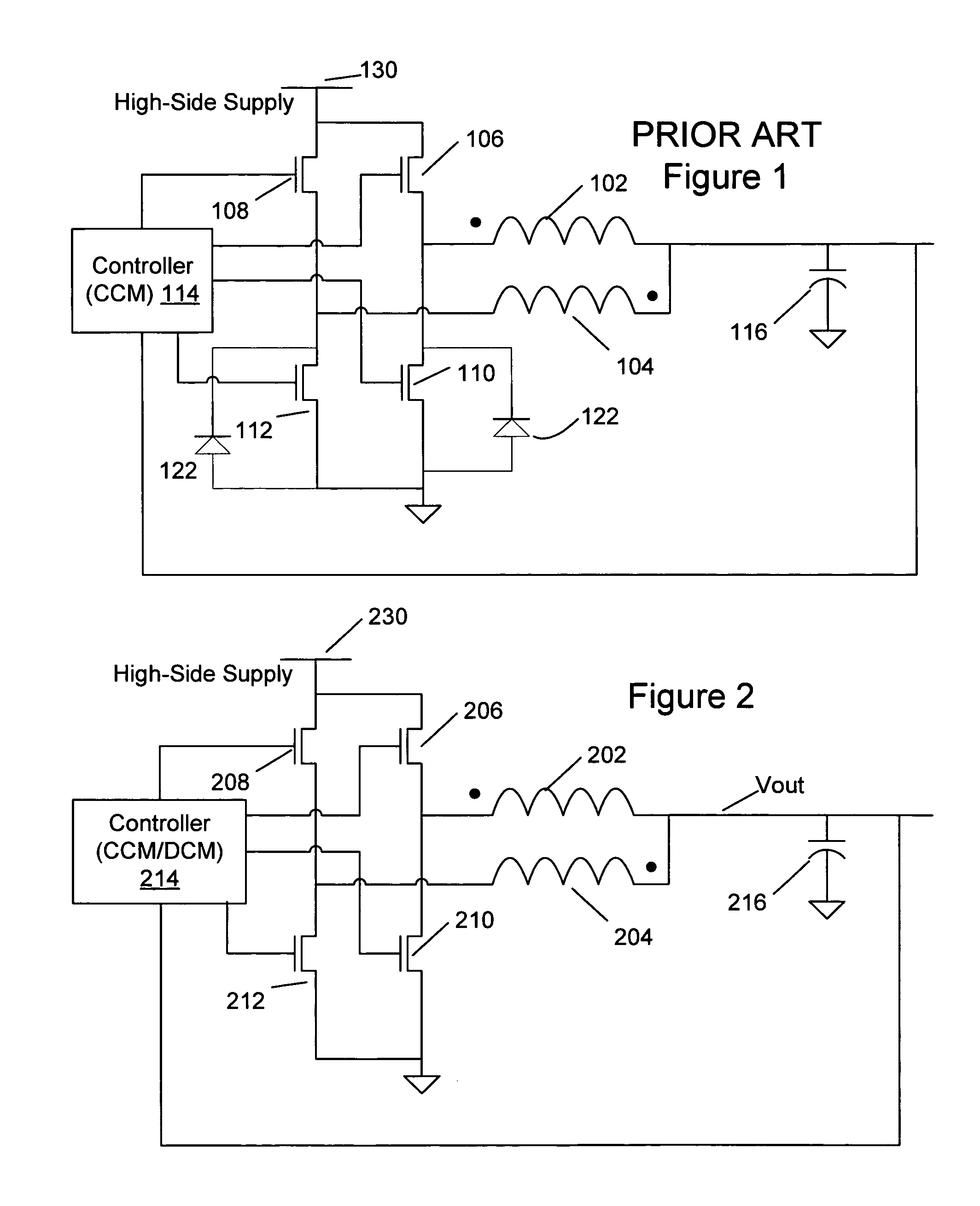
[0019]A two-phase buck-type voltage converter as described in U.S. Pat. No. 6,362,986 to Schultz (FIG. 1) has first 102 and second 104 magnetically coupled inductive windings. This converter has first 106 and second 108 high-side switches, typically implemented as high speed switching transistors, which in an embodiment are P-channel MOS transistors but in alternative embodiments are implemented as N-channel MOS, PNP-bipolar, or NPN-bipolar devices. This converter also has first 110 and second 112 low-side switches, a controller 114, and an output filter having at least one capacitor 116.

[0020]The prior-art voltage converter of U.S. Pat. No. 6,362,986 operates in continuous conduction mode (CCM). During CCM operation controller 114 monitors an output voltage at capacitor 116. In periodic steady-state, controller 114 produces pulses by turning on alternately one of the first 106 or second 108 high-side switches, which connect to the high side supply voltage 130, thereby building a cu...


PUM


Abstract

A multi-phase, coupled-inductor, DC-DC voltage converter operates in discontinuous conduction mode (DCM) when the system is operated at low output power demand. An embodiment of the converter switches to operating in continuous conduction mode (CCM) when the system is operated at high output power demand. Operation in single-drive and rotating phase DCM operation at low power are described. An alternative embodiment operates in a multiple-drive, rotating-phase, discontinuous conduction mode during at least one condition of output power demand.

Description

FIELD OF THE INVENTION[0001]The invention relates generally to switching power converters, and particularly to multiphase DC-to-DC converters having coupled inductors.BACKGROUND OF THE INVENTION[0002]Switching DC-to-DC power converters having a multi-phase coupled inductor topology like that described in U.S. Pat. No. 6,362,986 to Schultz, et al., the disclosure of which is incorporated herein by reference, are known in the art. These converters have advantages, including reduced ripple current in the inductors and switches allowing reduced per-phase inductance or reduced switching frequency, over converters having conventional multi-phase dc-dc converter topologies. Switching DC-to-DC converters as described in U.S. Pat. No. 6,362,986 typically operate in continuous conduction mode (CCM) for high efficiency while driving heavy loads.Load Variability[0003]DC-DC power converters are often used in applications where the load may vary considerably as a system operates.[0004]For example...

Claims


Application Information

Patent Timeline
Patent Type & Authority Patents(United States)
IPC IPC(8): G05F1/40
CPCH02M3/157H02M3/1584
Inventor STRATAKOS, ANTHONYLI, JIELIBERONJA, BILJANALIDSKY, DAVIDMCJIMSEY, MICHAELSCHULTZ, AARONSULLIVAN, CHARLES R.NICKEL, CHARLES
Owner VOLTERRA SEMICONDUCTOR
Why Eureka
Try Eureka